DLPC150
DATEN_CMD
PCLK
VSYNC_WE
HSYNC_CS
PDATA3
PDATA4
PDATA5
PDATA6
PDATA7
PDATA10
PDATA11
PDATA12
PDATA13
PDATA14
PDATA15
PDATA19
PDATA20
PDATA21
PDATA22
PDATA23
PDATA2
PDATA18
PDATA1
PDATA9
PDATA17
PDATA0
PDATA8
PDATA16
DLPA2005
SPI_CSZ
SPI_DIN
SPI_CLK
SPI_DOUT
RESETZ
SENS1
GPIO_3 (CS)
GPIO_2 (DOUT)
GPIO_1 (CLK)
GPIO_0 (DIN)
RESETZ
PARKZ
INTZ
0.2” TRP
VDDI
VOFFSET
VDD
VRESET
VBIAS
LS_OUT
VRST
VBIAS
VOFS
DMD Control
DMD Sub-LVDS
DMD Control
DMD Sub-LVDS
SPI0
SPI Flash
SPI_CLK
SPI_RX
SPI_TX
SPI_CS
TM4C1297
PJ6/LCDAC
PR0/LCDCP
PR1/LCDFP
PR2/LCDLP
PR4/LCDDATA00
PR5/LCDDATA01
PF7/LCDDATA02
PR3/LCDDATA03
PR6/LCDDATA04
PR7/LCDDATA05
PS4/LCDDATA06
PS5/LCDDATA07
PS6/LCDDATA08
PS7/LCDDATA09
PT0/LCDDATA10
PT1/LCDDATA11
PN7/LCDDATA12
PN6/LCDDATA13
PJ2/LCDDATA14
PJ3/LCDDATA15
PJ4/LCDDATA16
PJ5/LCDDATA17
PT2/LCDDATA18
PT3/LCDDATA19
PS0/LCDDATA20
PS1/LCDDATA21
PS2/LCDDATA22
PS3/LCDDATA23
PG7/SSI2CLK
PG5/SSI2XDAT0 (TX)
PG4/SSI2XDAT1 (RX)
PG6/SSI2FSS
SN74LVC2G125
SN74LVC1G125
PD2/I2C2SCL
PG3/I2C2SDA
IIC0_SCL
IIC0_SDA
LED_SEL
LED_SEL
PWM_IN
CMP_OUT
CMP_PWM
CMP_OUT
GPIO10/RC_CHARGE
PP0 (I)
PP1 (I)
PD3 (O)
TRIG_OUT_2
TRIG_OUT_!
TRIG_IN_1
Photodiode
LS
PJ7_O
PROJ_ON
LS
PLL_REFCLK
24MHz
SENS2
PROJ_ON
RESETZ
HOST_IRQ
PQ7 (I)
RESETZ
LS
PQ6 (I)
Logic
PE0 (O)
PE1 (O)
PD2/I2C8SCL
OPA567
EN
OUT
External Power Supply Requirements
www.ti.com
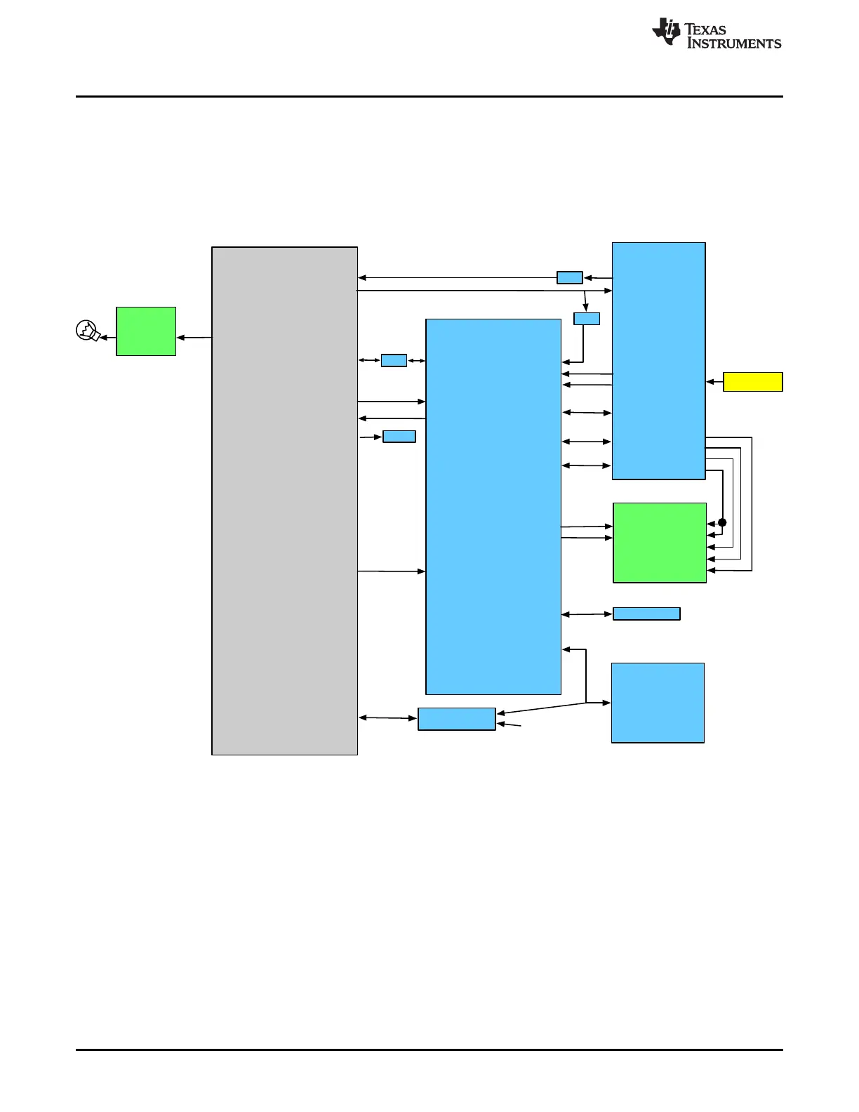
Figure 4-3 shows the Tiva connections to the DLPC150 controller board. Tiva powers up the DLP
subsystem through PJ7. The TIva's LCD interface is connected to the DLPC150 Parallel Port interface.
Through this interface 24 patterns are transmitted per frame. DLPC150 sends two interrupts to the Tiva to
indicate when a pattern is exposed (TRIG_OUT_2) and when a new frame begins (TRIG_OUT_1). For
DLPC150 firmware updates, the Tiva con write to the DLPC150 serial flash through its SSI2 peripheral
when the DLP subsystem is powered down. Tiva's PD2 controls the lamp. A lamp photodiode is measured
by the DLPA2005 when a scan occurs. The value of the photodiode is transmitted to the DLPC150 and
then to the Tiva. This photodiode measures the lamp intensity.
Figure 4-3. DLP NIRscan Nano Tiva Connections to DLPC150 Controller Board
34
DLP NIRscan Nano Hardware DLPU030B–June 2015–Revised July 2015
Submit Documentation Feedback
Copyright © 2015, Texas Instruments Incorporated