EasyManuals Logo

Texas Instruments DLP NIRscan User Manual

Texas Instruments DLP NIRscan
73 pages
To Next Page IconTo Next Page
To Previous Page IconTo Previous Page
Page #57 background imageLoading...
Page #57 background image
www.ti.com
Trigger Connector
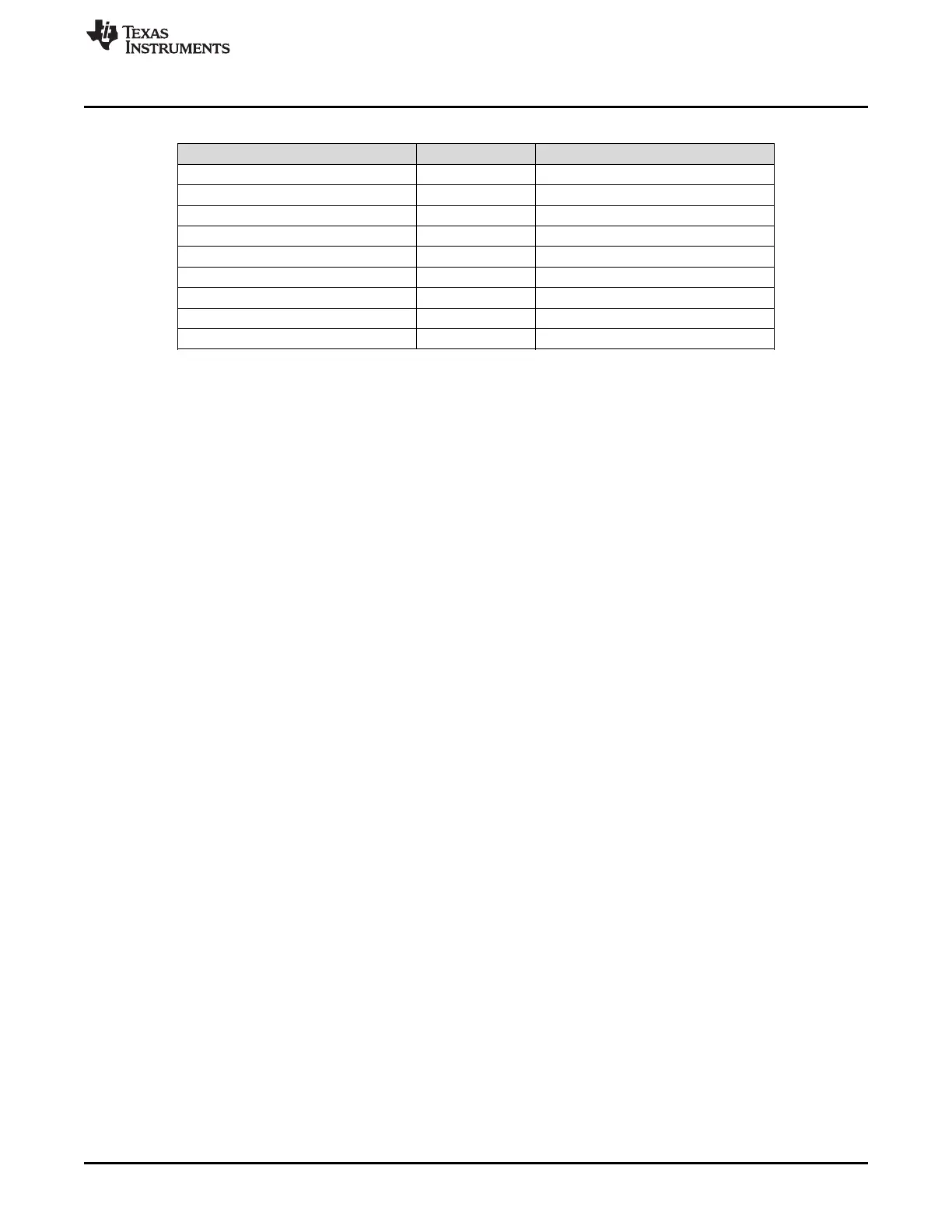
Table F-5. Trigger Connector (DLPC150 J500)
DESCRIPTION PIN SUPPLY RANGE
Tiva PD2 (lamp control) 1 3.3 V
TRIG_IN_1 2 3.3 V
Ground 3 Ground
DLPC150 GPIO_17 4 3.3 V
DLPC150 GPIO_18 5 3.3 V
Ground 6 Ground
TRIG_OUT_2 (frame trigger) 7 3.3 V
TRIG_OUT_1 (pattern trigger) 8 3.3 V
Ground 9 Ground
57
DLPU030BJune 2015Revised July 2015 DLP NIRscan Nano Connectors
Submit Documentation Feedback
Copyright © 2015, Texas Instruments Incorporated

Table of Contents

Questions and Answers:

Question and Answer IconNeed help?

Do you have a question about the Texas Instruments DLP NIRscan and is the answer not in the manual?

Texas Instruments DLP NIRscan Specifications

General IconGeneral
BrandTexas Instruments
ModelDLP NIRscan
CategoryMotherboard
LanguageEnglish

Related product manuals