eZ-FET
Emulator
MCU
Isolation
Jumper Block
Spy-Bi-Wire (SBW)
Emulation
Application UART
3.3V Power
5V Power
Target
MSP430FR5969
MCU
eZ-FETMSP430FR5969 Target
USB Connector
in out
LDO
BoosterPack Header
BoosterPack Header
USCI A0
USB
Hardware
www.ti.com
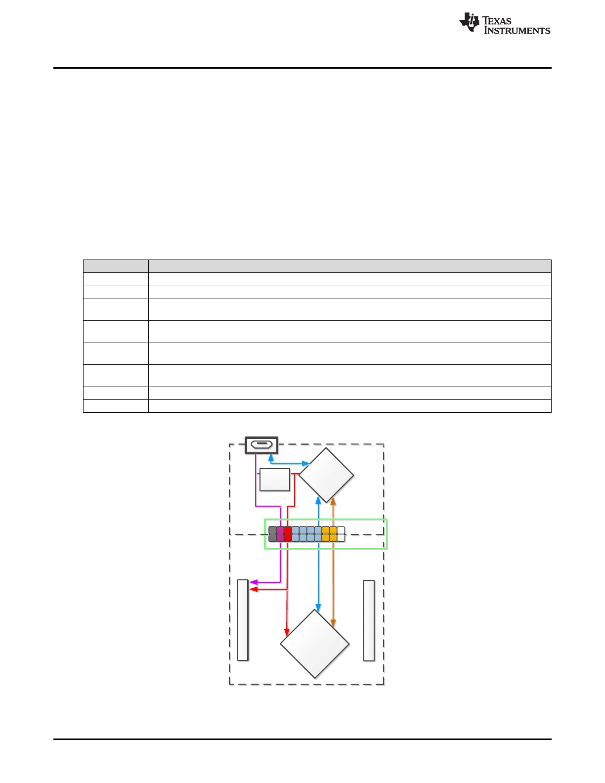
2.3.4 Emulator Connection – Isolation Jumper Block
The isolation jumper block at Jumper J13 allows the user to connect/disconnect signals that cross from
the eZ-FET domain into the FR5969 target domain. This includes eZ-FET Spy-Bi-Wire signals, application
UART signals, and 3V3 and 5V power (see Table 3).
Reasons to open these connections:
• To remove any and all influence from the eZ-FET emulator for high accuracy target power
measurements
• To control 3-V and 5-V power flow between eZ-FET and target domains
• To expose the target MCU pins for other use than onboard debugging and application UART
communication
• To expose programming and UART interface of the eZ-FET so it can be used for devices other than
the onboard MCU.
Table 3. Isolation Block Connections
Jumper Description
GND Ground
V+ 3.3-V rail, derived from VBUS by an LDO in the eZ-FET domain
Backchannel UART: Ready-To-Send, for hardware flow control. The target can use this to indicate whether 'it is
RTS >>
ready to receive data from the host PC. The arrows indicate the direction of the signal.
Backchannel UART: Clear-To-Send, for hardware flow control. The host PC (through the emulator) uses this to
CTS <<
indicate whether or not it is ready to receive data. The arrows indicate the direction of the signal.
Backchannel UART: the target FR5969 receives data through this signal. The arrows indicate the direction of the
RXD <<
signal.
Backchannel UART: the target FR5969 sends data through this signal. The arrows indicate the direction of the
TXD >>
signal.
RST Spy-Bi-Wire emulation: SBWTDIO data signal. This pin also functions as the RST signal (active low)
TST Spy-Bi-Wire emulation: SBWTCK clock signal. This pin also functions as the TST signal
Figure 10. eZ-FET Isolation Jumper Block Diagram
14
MSP430FR5969 LaunchPad™ Development Kit (MSP
‑
EXP430FR5969) SLAU535B–February 2014–Revised July 2015
Submit Documentation Feedback
Copyright © 2014–2015, Texas Instruments Incorporated

 Loading...


