J3
V+
J13
Debugger
J10
J12
External
VCC
GND
GND
J9
J2
Bypass
Use
Charge
J11
External
J4
J5
VCC
GND
GND
J1
Current
MSP430FR5969
target and
BoosterPack
Target
MSP430FR5969
Device
Measure
External Power
Source Configuration
J3
V+
J13
Debugger
J10
J12
External
VCC
GND
GND
J9
J2
Bypass
Use
Charge
J11
J4
J5
VCC
GND
GND
J1
Current
MSP430FR5969
target and
BoosterPack
Target
MSP430FR5969
Device
Measure
VCC
GND
BoosterPack Power
Configuration
Hardware
www.ti.com
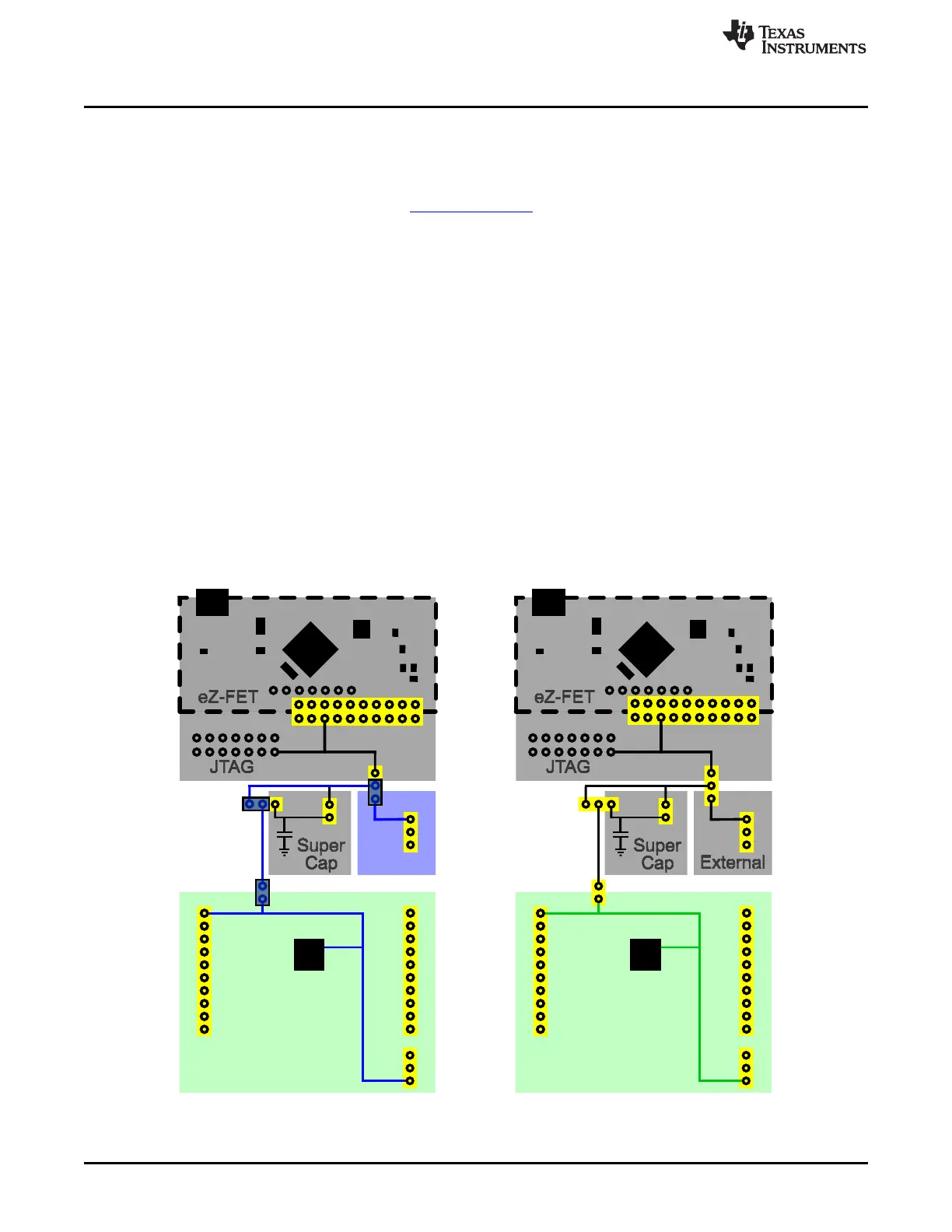
2.4.3 External Power Supply
An extra header J12 is present on the board to supply external power. When supplying external power,
jumper J10 must be set to "External." It is important to understand the device voltage operation
specifications when supplying external power. The MSP430FR5969 has an operating range of 1.8 V to 3.6
V. More information can be found in the device data sheet.
For power configuration diagram, see Figure 13.
2.4.4 BoosterPack
In some use cases it might be required to power the board from a BoosterPack. When powered from a
BoosterPack, the BoosterPack voltage should be across J4 Pin 1 (Vcc) and J5 Pin 20 (GND). This
complies with the BoosterPack pinout shown in Section 2.5. These pins are connected directly to the
FR5969 target device, and do not require any specific jumper configuration. Header J1 also provides
power directly to the target device.
Because J1 and the BoosterPack headers are connected directly to the target device V
cc
, there are two
primary consequences:
• The super cap cannot charge through J11. Use of the super cap with this power scenario is not
recommended.
• Current of the target device through J9 cannot be measured. It is best to remove J9 in this scenario to
prevent back-powering of any additional circuitry such as the eZ-FET.
For power configuration diagram, see Figure 13.
Figure 13. External Power Configuration – External and BoosterPack
18
MSP430FR5969 LaunchPad™ Development Kit (MSP
‑
EXP430FR5969) SLAU535B–February 2014–Revised July 2015
Submit Documentation Feedback
Copyright © 2014–2015, Texas Instruments Incorporated

 Loading...


