WAKE INT
(A)(B)
XCLKOUT
Address/Data
(internal)
t
d(WAKE−IDLE)
t
w(WAKE−INT)
151
TMS320F28069
,
TMS320F28068
,
TMS320F28067
,
TMS320F28066
TMS320F28065, TMS320F28064, TMS320F28063, TMS320F28062
www.ti.com
SPRS698F –NOVEMBER 2010–REVISED MARCH 2016
Submit Documentation Feedback
Product Folder Links: TMS320F28069 TMS320F28068 TMS320F28067 TMS320F28066 TMS320F28065
TMS320F28064 TMS320F28063 TMS320F28062
Detailed DescriptionCopyright © 2010–2016, Texas Instruments Incorporated
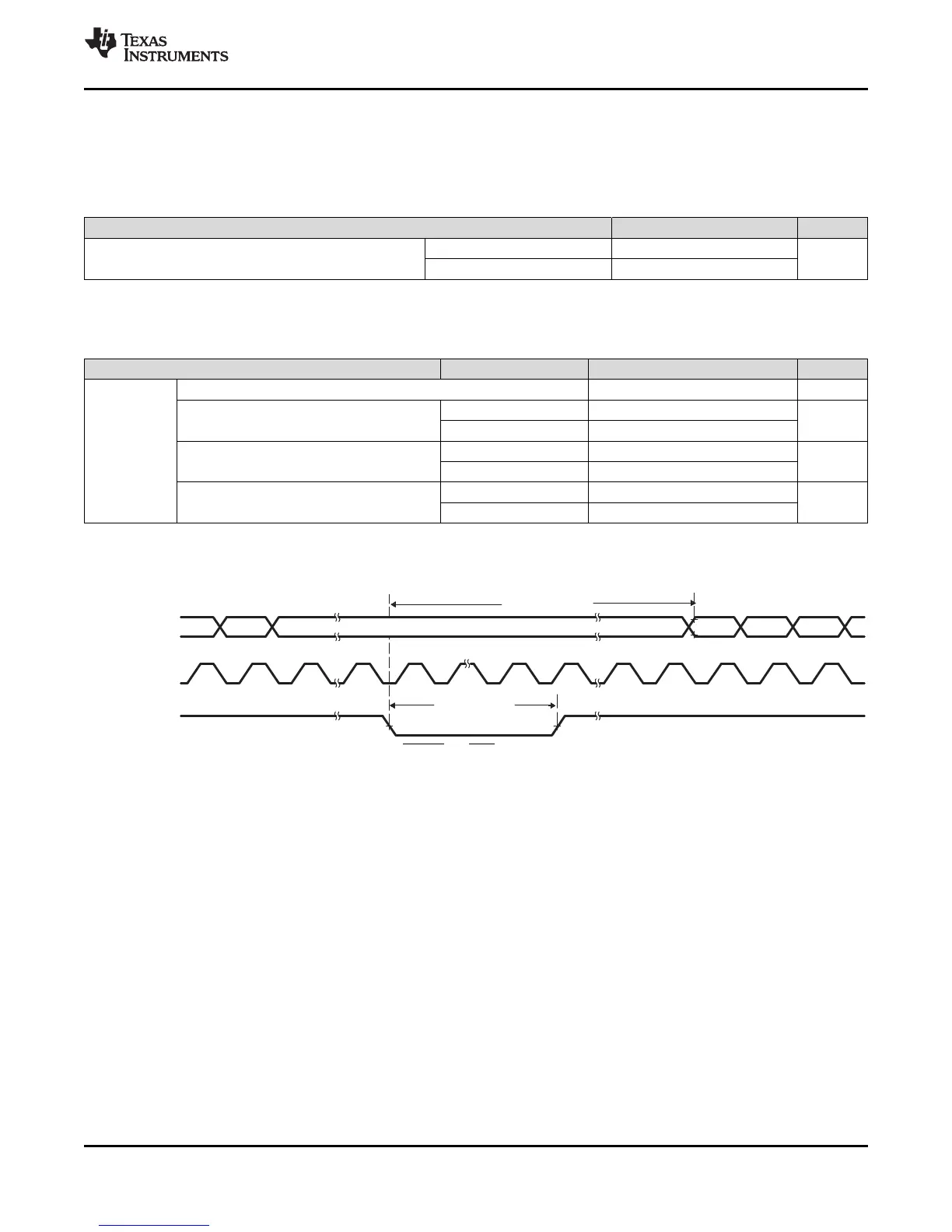
6.9.15.1.4 Low-Power Mode Wakeup Timing
Table 6-77 shows the timing requirements, Table 6-78 shows the switching characteristics, and Figure 6-
60 shows the timing diagram for IDLE mode.
(1) For an explanation of the input qualifier parameters, see Table 6-76.
Table 6-77. IDLE Mode Timing Requirements
(1)
MIN MAX UNIT
t
w(WAKE-INT)
Pulse duration, external wake-up signal
Without input qualifier 2t
c(SCO)
cycles
With input qualifier 5t
c(SCO)
+ t
w(IQSW)
(1) For an explanation of the input qualifier parameters, see Table 6-76.
(2) This is the time taken to begin execution of the instruction that immediately follows the IDLE instruction. execution of an ISR (triggered
by the wake-up) signal involves additional latency.
Table 6-78. IDLE Mode Switching Characteristics
(1)
over recommended operating conditions (unless otherwise noted)
PARAMETER TEST CONDITIONS MIN MAX UNIT
t
d(WAKE-IDLE)
Delay time, external wake signal to program execution resume
(2)
cycles
• Wake-up from flash
– Flash module in active state
Without input qualifier 20t
c(SCO)
cycles
With input qualifier 20t
c(SCO)
+ t
w(IQSW)
• Wake-up from flash
– Flash module in sleep state
Without input qualifier 1050t
c(SCO)
cycles
With input qualifier 1050t
c(SCO)
+ t
w(IQSW)
• Wake-up from SARAM
Without input qualifier 20t
c(SCO)
cycles
With input qualifier 20t
c(SCO)
+ t
w(IQSW)
A. WAKE INT can be any enabled interrupt, WDINT or XRS. After the IDLE instruction is executed, a delay of
five OSCCLK cycles (minimum) is needed before the wake-up signal could be asserted.
B. From the time the IDLE instruction is executed to place the device into low-power mode (LPM), wakeup should not be
initiated until at least four OSCCLK cycles have elapsed.
Figure 6-60. IDLE Entry and Exit Timing