INT12
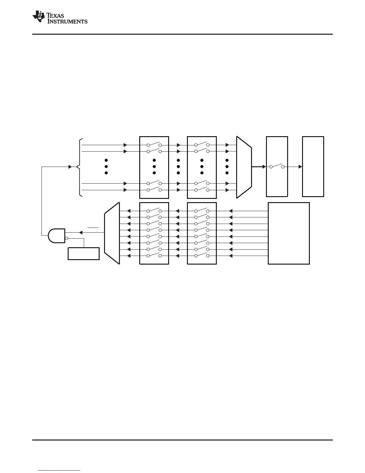
MUX
INT11
INT2
INT1
CPU
(Enable)(Flag)
INTx
INTx.8
PIEIERx[8:1] PIEIFRx[8:1]
MUX
INTx.7
INTx.6
INTx.5
INTx.4
INTx.3
INTx.2
INTx.1
From
Peripherals
or
External
Interrupts
(Enable) (Flag)
IER[12:1]IFR[12:1]
Global
Enable
INTM
1
0
PIEACKx
(Enable/Flag)
75
TMS320F28069
,
TMS320F28068
,
TMS320F28067
,
TMS320F28066
TMS320F28065, TMS320F28064, TMS320F28063, TMS320F28062
www.ti.com
SPRS698F –NOVEMBER 2010–REVISED MARCH 2016
Submit Documentation Feedback
Product Folder Links: TMS320F28069 TMS320F28068 TMS320F28067 TMS320F28066 TMS320F28065
TMS320F28064 TMS320F28063 TMS320F28062
Detailed DescriptionCopyright © 2010–2016, Texas Instruments Incorporated
Eight PIE block interrupts are grouped into one CPU interrupt. In total, 12 CPU interrupt groups, with
8 interrupts per group equals 96 possible interrupts. Table 6-17 shows the interrupts used by 2806x
devices.
The TRAP #VectorNumber instruction transfers program control to the interrupt service routine
corresponding to the vector specified. TRAP #0 attempts to transfer program control to the address
pointed to by the reset vector. The PIE vector table does not, however, include a reset vector. Therefore,
TRAP #0 should not be used when the PIE is enabled. Doing so will result in undefined behavior.
When the PIE is enabled, TRAP #1 through TRAP #12 will transfer program control to the interrupt service
routine corresponding to the first vector within the PIE group. For example: TRAP #1 fetches the vector
from INT1.1, TRAP #2 fetches the vector from INT2.1, and so forth.
Figure 6-17. Multiplexing of Interrupts Using the PIE Block