28
Table 4-2: Rear panel connections and controls
Number Item Description Section
4
Remote Out
connector
RJ-45 type connector, used for chaining power supplies to form
a serial communication bus.
7.3
7.4
5
Programming
and
Monitoring
connector
Connector for remote analog interface. Includes output voltage
and current limit programming and monitoring signals, Shut-off
control (electrical signal), Enable/Disable control (dry-contact),
power supply ok (PS_OK) signal and operation mode (CV/CC)
signal.
4.5
6
SW1 Setup
switch
Nine position DIP switch for selecting remote programming and
monitoring modes for Output Voltage, Current Limit and other
control functions.
4.4
4.4.1
4.4.2
7
Remote
sense
connector
Connector for making remote sensing connections to the load
for regulation of the load voltage and compensation of load wire
drop.
3.8.2
3.10.2
3.10.3
8
Blank
Sub-plate
Blank sub-plate for standard units. Isolated Remote Analog
programming connector for unit equipped with Isolated Analog
control option. IEEE connector for units equipped with IEEE
programming option (shown).
9 IEEE switch
Two position DIP switch for selecting IEEE mode or RS232/485
mode when IEEE option is installed.
10
Ground
screw
M4x8 screw for chassis ground connection.
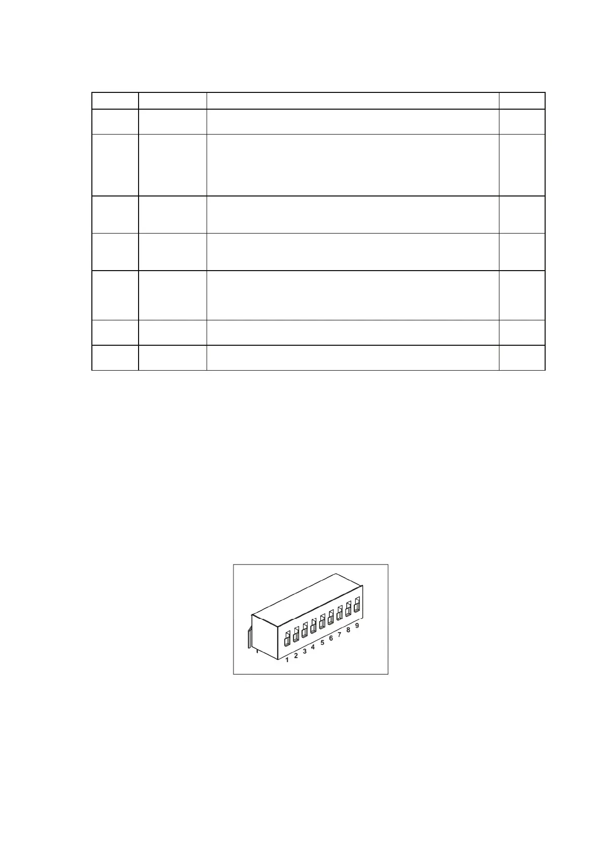
3.4. REAR PANEL SW1 SETUP SWITCH
The SW1 Setup switch (see Fig.4-3) is a 9-position DIP switch that allows the user to choose the
following:
- Internal or remote programming for Output Voltage and Current Limit.
- Remote voltage or resistive programming of Output Voltage and Output Current limit.
- Select range of remote voltage and resistive programming.
- Select range of Output Voltage and Output Current monitoring.
- Select the Remote Shut-Off control logic.
- Select between RS232 or RS485 communication interface.
- Enable or disable the rear panel Enable/Disable control (dry contact).
Fig.4-3: SW1 setup DIP switch