40
5.14.2 Series connection for positive and negative output voltage
In this mode, two units are configured as a positive and negative output. Set the current limit of
each power supply to the maximum that the load can handle without damage. It is recommended
that diodes be connected in parallel with each unit output to prevent reverse voltage during
start-up or in case one of the units shuts down. Each diode should be rated to at least the power
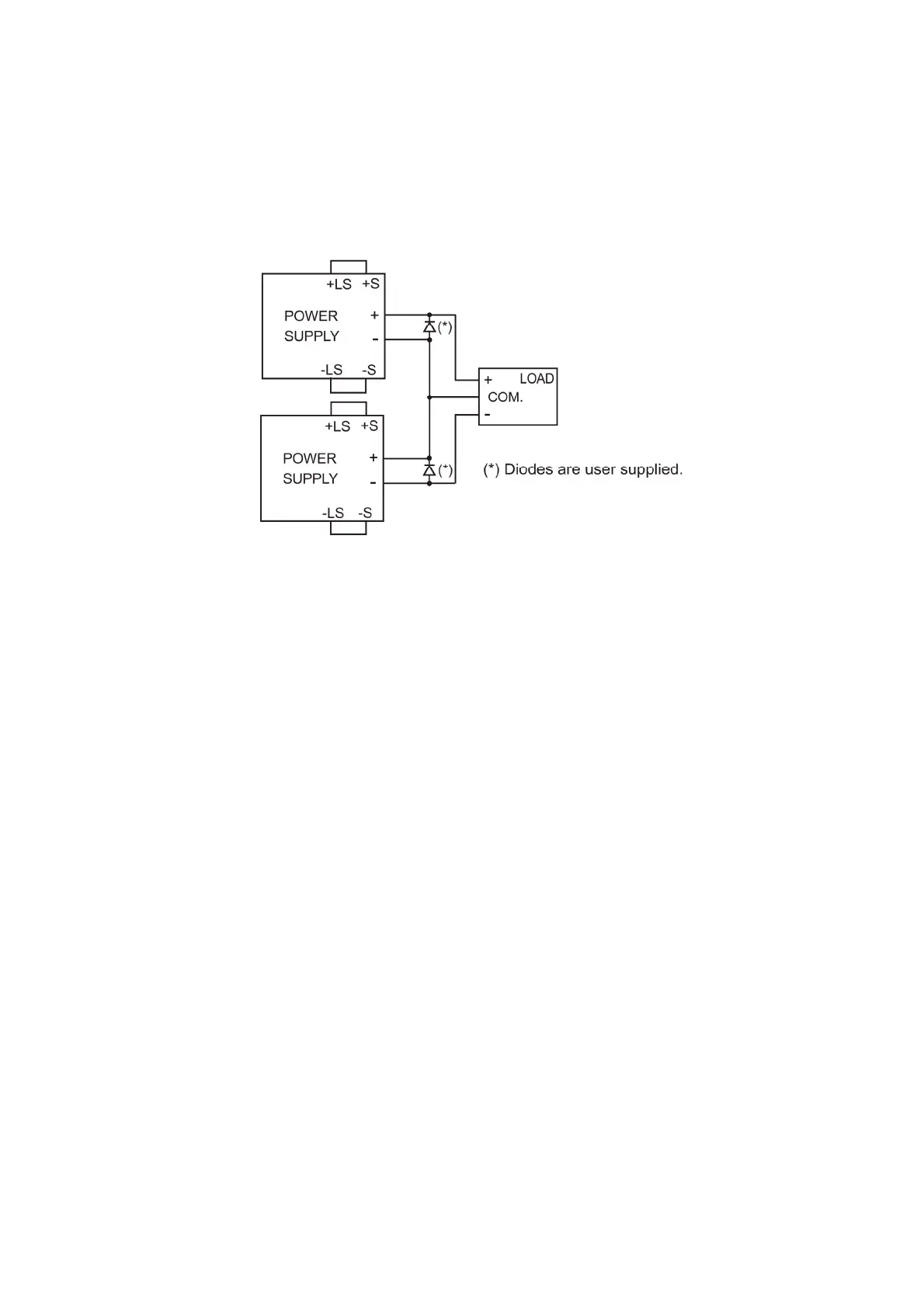
supply rated output voltage and output current. Refer to Fig.5-3 for this operating mode.
Fig.5-3: Series connection for positive/negative output voltages
Remote programming in series operation for positive and negative output voltage
1. Programming by external voltage: The analog programming circuits of this power supply are
referenced to the negative Sense potential.
Therefore, the circuits used to control each series
connected unit must be separated and floated from
each other.
2. Using the SO function and PS_OK The Shut-Off and PS_OK circuits are referenced to the
signal: isolated interface common, IF_COM (J1-2, 3).
The IF_COM terminals of the units can be connected
to obtain a single control circuit for the power supplies
connected in series.
3. Programming by external resistor: Programming by external resistor is possible. Refer to
section 6-5 for details.
4. Programming via the Serial The communication port is referenced to the IF_COM
Communication port (RS232/RS485): which is isolated from the power supply output potential.
Therefore power supplies connected in series can be
chained using the Remote-In and Remote-Out
connectors. Refer to chapter 7 for details.