36
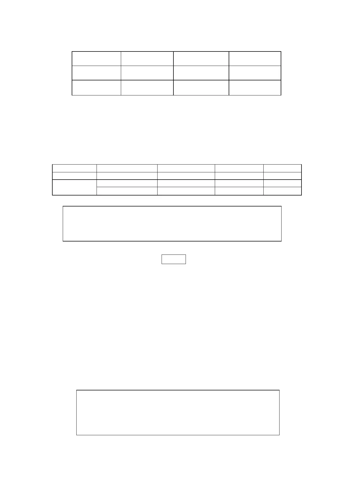
Table 5-2: SO logic selection
SW1-5 setting
SO signal level
J1-2(3), 15
Power supply
output
Display
Down (default) 2-15V or Open
0-0.6V or Short
On
Off
Voltage/Current
“SO”
Up
2-15V or Open
0-0.6V or Short
Off
On
“SO”
Voltage/Current
4.8. ENABLE/DISABLE CONTROL VIA REAR PANEL J1 CONNECTOR
Contacts 1 and 14 of J1 (Fig.4-2, Item 5) serve as Output Enable/Disable terminals by switch or relay.
This function is enabled or disabled by the SW1 Setup switch position 9. Refer to Table 5-3 for
Enable/Disable function andSW1setting..
Table 5-3: Enable/Disable function and SW1 setting
SW1-9 setting Enable/Disable inputs Power supply output Display ALARM LED
Down (default) Open or Short On Voltage/Current Off
Open Off “ENA” Blinking
Up
Short On Voltage/Current Off
NOTE
If the Enable/Disable inputs are opened in Safe Start mode, it is
required to short the Enable /Disable inputs and then press OUTPUT
button or send OUT1 command to resume operation. But in
auto-restart mode set these inputs short, and then the output will rise
up automatically after output-off by this function.
4.9. CV/CC SIGNAL
CV/CC signal indicates the operating mode of the power supply, Constant Voltage or Constant
Current.
CV/CC signal is an open collector output with a 30V parallel zener, at J1-13, referenced to the COM
potential at J1-12 (connected internally to the negative sense potential). When the power supply
operates in Constant Voltage mode, CV/CC output is open. When the power supply operates in
Constant Current mode, CV/CC signal output is low (0-0.6), with maximum 10mAsink current
.
CAUTION
To prevent possible damage to the unit, do not connect any of the
Enable/Disable inputs to the positive or negative output potential
.
CAUTION
Do not connect CV/CC signal to a voltage source higher than 30VDC.
Always connect CV/CC signal to the voltage source with a series resistor
to limit the sink current to less than 10mA.