AS 680/682
Subsystem Description Description, Operation and Maintenance
ADS−B
2−10 Ed. 10.07
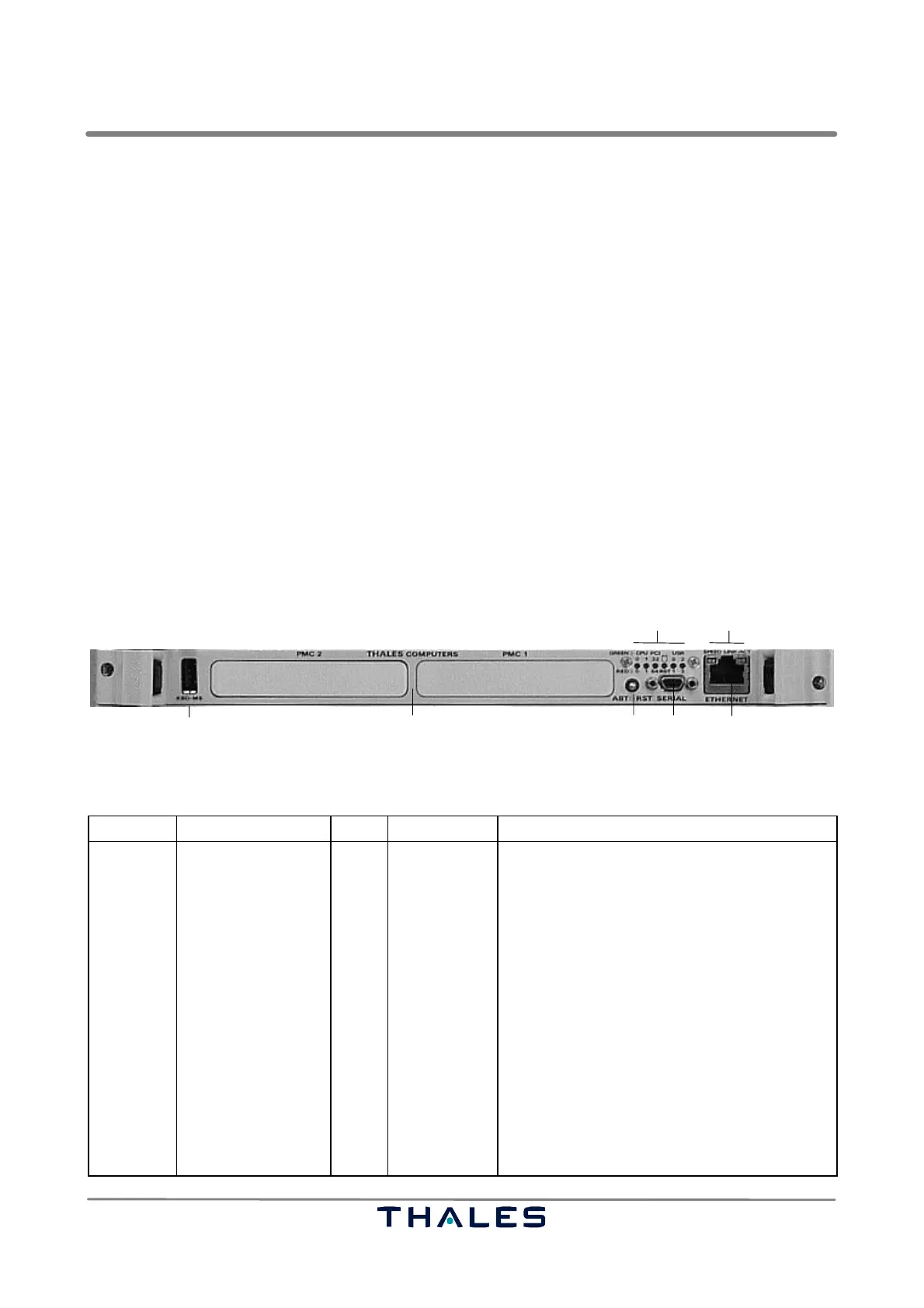
2.1.4.4 Single Board Computer (SBC)
See Fig. 2−11.
Control of the SPU, ADS−B process network and communication to the ATC application, the RCMS
or LCMS, is performed by the Single Board Computer (SBC). The SBC is a highly integrated, VMEbus
processor card based on the Thales product PowerEngine 7. The SBC is running under Linux.
The SBC provides the two Ethernet interfaces 0 and 1 of the Ground Station. The main external inter-
face 1 is used to connect the Ground Station to the actual ATM application and the Remote Control
and Monitoring System (RCMS) via an operational data network. The auxiliary Ethernet interface 0
is located at the front panel of the GTS module but provided by the SBC as well. Both interfaces are
separately driven by individual Ethernet controllers.
In addition to that, the SBC is equipped with a V.24 serial port, to which the local the Local Control
and Monitoring System (LCMS), consisting of a maintenance Laptop PC, can be connected using
a standard terminal program (minicom under Linux). This port allows to open a local command shell
and to perform initial configuration for the Ground Station (refer also to section 3.2.7). If the Laptop
does not include a serial connector but an USB port a special conversion cable (USB to Serial) has
to be used which is optional available.
The following table gives a definition of the indicators and controls of the SBC module.
Ethernet
Serial V.24Board reset
LED
(RJ45, 10/100Base−T)
MicroSubD
Expansion slots (n.a.)Keyboard/Mouse (n.a.)
Ethernet LED
Fig. 2−11 Single Board Computer (SBC)
Board Indicator Color Control Function of control or indicator (lit or flashing)
SBC
LED, CPU (0)*
LED, CPU (1)*
LED, PCI (32/64)*
LED, RST*
red
green
red
green
red
green
red
green
Abort/Reset Key switch, neutral position: mid; manual reset
of SBC or abort program execution
If lit, it indicates a checkstop condition.
If lit, it indicates an activity of the CPU0
processor. Active when the CPU0 transfers
data on the system bus.
If lit, it indicates a checkstop condition.
If lit, it indicates an activity of the CPU1
processor. Active when the CPU1 transfers
data on the system bus.
Only used if CPU 1 option is available.
Indicates an activity on the 32−bit PCI bus.
Indicates an activity on the 64−bit PCI bus.
If lit, indicates that board is in reset state.
If lit, this indication is meaningless.