AS 680/682
Description, Operation and Maintenance Installation and Setup
ADS−B
3−7Ed. 10.07
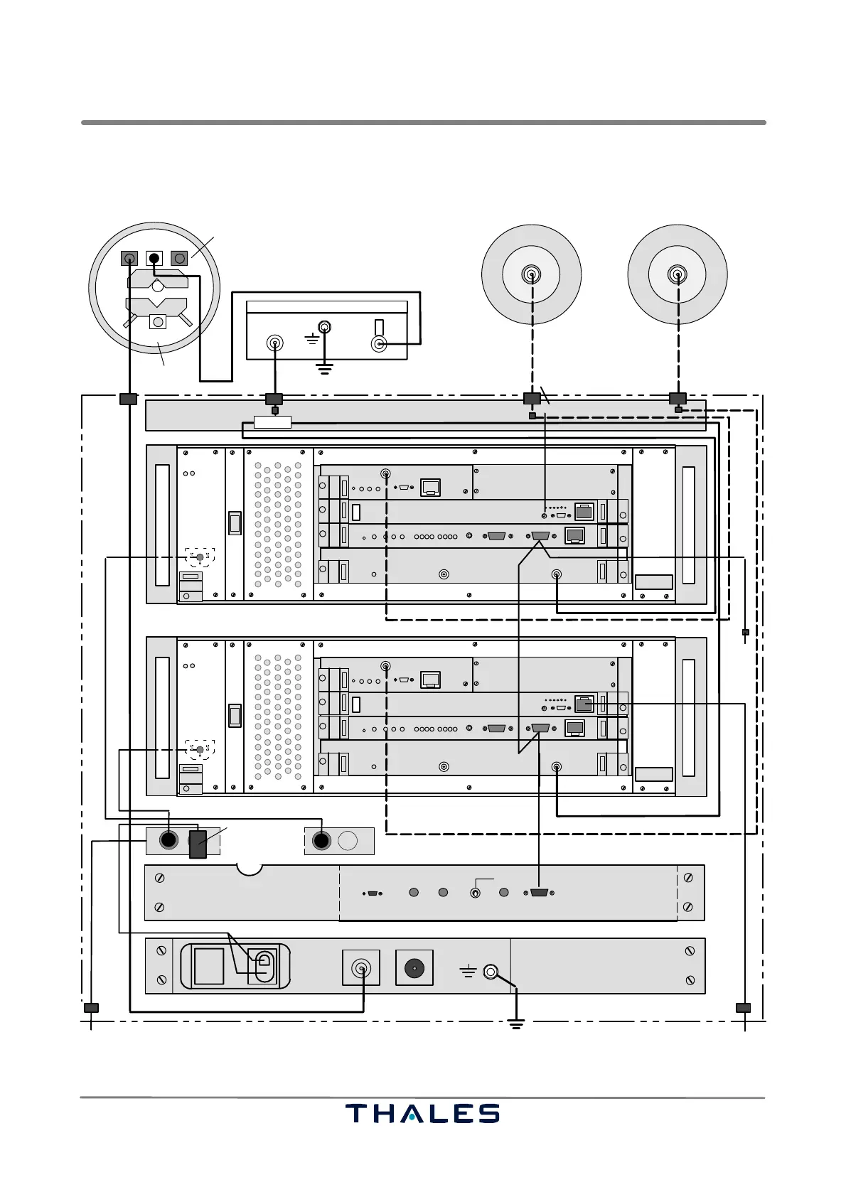
3.1.5.2 Ground Station AS 682
OL
M1 M2
ANTENNA
connector
NNN
Fault
Power
THALES Mode S Ground Station SPU
SPBRXU
GTS
DG14
I
0
ADS−B RX antenna GPS antenna (2)
bottom view
bottom view
STANDBY
SPU, front view)
outdoor
AS682 cabinet
RF out
TNC
LP=Lightning protection
SMA
SMA
* Connector definitions: N, SMA, TNC, N+LP, MicroSub
N+LP
N+LP
RJ45
SubD9
27288 04140
1)
1)
1) Provided by customer
** if not connected to antenna, it must be terminated
not used
up to 30 m
up to 10 m
NOTE:
RF cable to GPS antenna: 1/4" cellflex or similar
VAC 100...240 V
AAU
RF cable to RX antenna: 1/2 cellflex or similar
Power
THALES
ADS−B SITE MONITOR
MAINTENANCE TX FAULT
SM, front view
MicroSubD
SubD9
RF out 1** RF out 2**
SM, rear view
20...28 VDC
NN
1)
PE
+
−
N+LP
SM1
SM1
SubD15
to Data switch
DC in 24 V nom
RF out
+12V DC in
RF in
N* N*
LP
1)
PE
up to 2m
1)
Mains sockets
230 VAC
to UPS mains distribution
RJ45
plug
N
mains
top
bottom
(2)
AC/DC plug−in
240xx 28xxx
SM Status
not used
with 50 ohm
27288 04059
27288 04142
if not used terminate
with 50 ohm
GPS antenna (1)
bottom view
RF out
TNC
1)
up to 10 m
Fault
Power
THALES Mode S Ground Station SPU
SPBRXU
GTS
DG14
I
0
SMA
SMA
RJ45
SubD9
1)
VAC 100...240 V
SubD15
N
NN
SPU, front view)
(1)
Exchange Panel 4/2
N+LP
27288 04141
27288 04140
status
doors
Fig. 3−12 System cabling ADS−B Ground Station AS 682 (1)