cutmaster 102
INSTALLATION 3-2 Manual 0-4998
3.03 Primary Input Power Connections
CAUTION
Check your power source for correct voltage before plugging in or connecting the unit. Check the Voltage Selector
at the rear of the unit for correct setting before plugging in or connecting the unit. The primary power source, fuse,
and any extension cords used must conform to local electrical code and the recommended circuit protection and
wiring requirements as specified in Section 2.
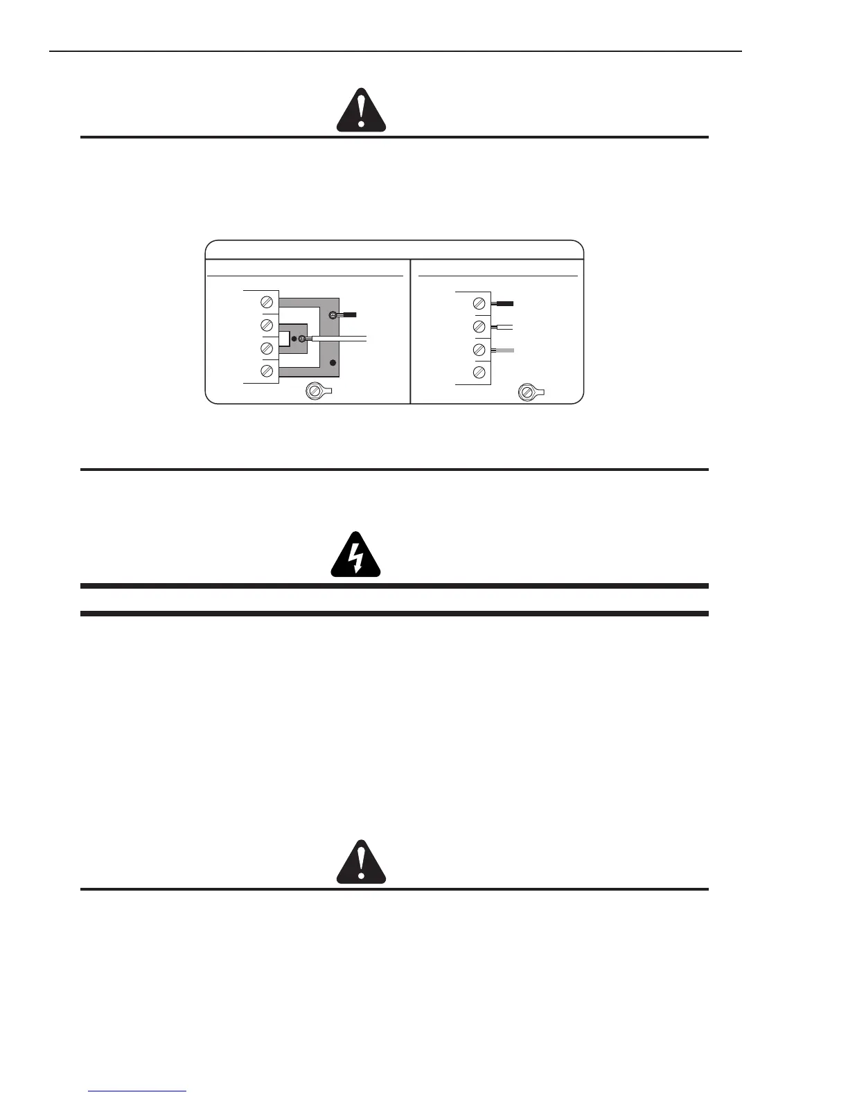
The following illustration and directions are for changing phase of the power supply.
Art # A-08493
Input Power Cable Connections
Three-Phase (3ø)
Store copper jumpers on base plate
Single-Phase (1ø) and Jumper Settings
GND
L1
L2
L3
L4
GND
L1
L2
L3
L4
Single and Three Phase Input Power Wiring
NOTE
There are two jumpers used for the single phase 230V setting and none for three phase.
A. Connections to Single Phase Input Power
WARNING
Disconnect input power from the power supply and input cable before attempting this procedure.
These instructions are for changing the input power and or cable on the 208/230, 400, 460 VAC Power
Supply to Single - Phase input power.
1. Remove the Power Supply cover per instructions found in section 5.
2. Disconnect the original input power cable from the main input contactor and the chassis ground
connection.
3. Loosen the through - hole protector on the back panel of the power supply. Pull the original
power cable out of the power supply.
4. If the power cable being used is not the factory - supplied cable, use a three - conductor input
power cable for the voltage desired and strip back the insulation on the individual wires.
5. Pass the cable being used through the access opening in the back panel of the power supply. Re-
fer to Section 2 for power cable specications.
CAUTION
The primary power source and power cable must conform to local electrical code and the recommended circuit
protection and wiring requirements (refer to table in Section 2).