EasyManuals Logo

Thermal Dynamics CUTMASTER 102 Service Manual

Thermal Dynamics CUTMASTER 102
120 pages
To Next Page IconTo Next Page
To Previous Page IconTo Previous Page
Page #94 background imageLoading...
Page #94 background image
cutmaster 102
PARTS LIST 6-4 Manual 0-4997
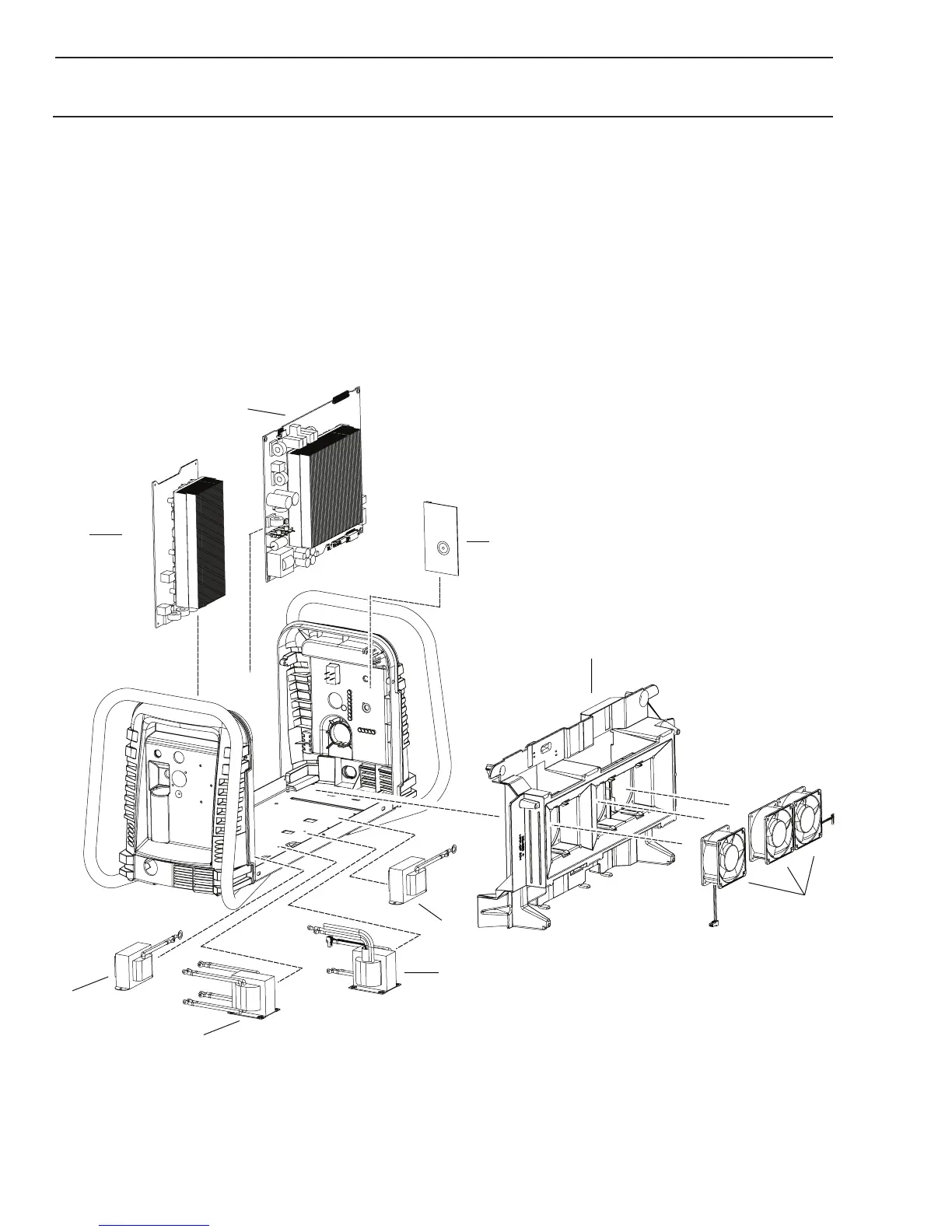
6.06 Left Side Replacement Parts
Item # Qty Description Ref Catalog #
1 1 Main PCB Assembly PCB1 9-0108
1b 1 Main PCB Assembly 40 Amp PCB5 9-0194
2 1 Logic PCB PCB3 9-0107*
3 1 Center Chassis Molded Plastic 9-0190
4 1 Fan, (3 total) MOT1-3 9-0104
5 1 Transformer, Main T1 9-0106
5b 1 Transformer, Main 60 Amp T2 9-0196
6 1 Inductor, Output L1 9-0105
6b 1 Inductor, Output 40 Amp L2 9-0195
Not Shown:
1 Power Cable Strain Relief, for all units 9-0111
1 Input Power Cable 230 V with plug, 9-0191
1 Hi/Lo voltage selection switch SW2 9-0110
1b
2
5
6
Art # A-08560
1
3
4
6b
5b

Table of Contents

Questions and Answers:

Question and Answer IconNeed help?

Do you have a question about the Thermal Dynamics CUTMASTER 102 and is the answer not in the manual?

Thermal Dynamics CUTMASTER 102 Specifications

General IconGeneral
BrandThermal Dynamics
ModelCUTMASTER 102
CategoryWelding System
LanguageEnglish

Related product manuals