cutmaster 102
PARTS REPLACEMENT 7-4 Manual 0-4998
G. Logic PCB (PCB3) Replacement
Tools required: T20 Torx Driver Flat Screw Driver, ½”
wrench
1. Remove the cover per subsection 7.04A
2. Remove the two large and one small gas hoses
from the pressure regulator per subsection
7.05C.
3. Unplug the connector J2 from the Main PCB.
4. Disconnect cable from the Pressure Transducer
5. Disconnect front panel from base per subsection
7.04D
6. Remove the Current Control Potentiometer Knob
and nut securing the potentiometer shaft to the
front panel per subsection 7.05A
7. Remove the Function Control Switch Knob and
the nut securing the switch shaft to the front
panel per subsection 7.05B.
8. Install the replacement Logic PCB by reversing
the above steps.
9. Reinstall the power supply cover.
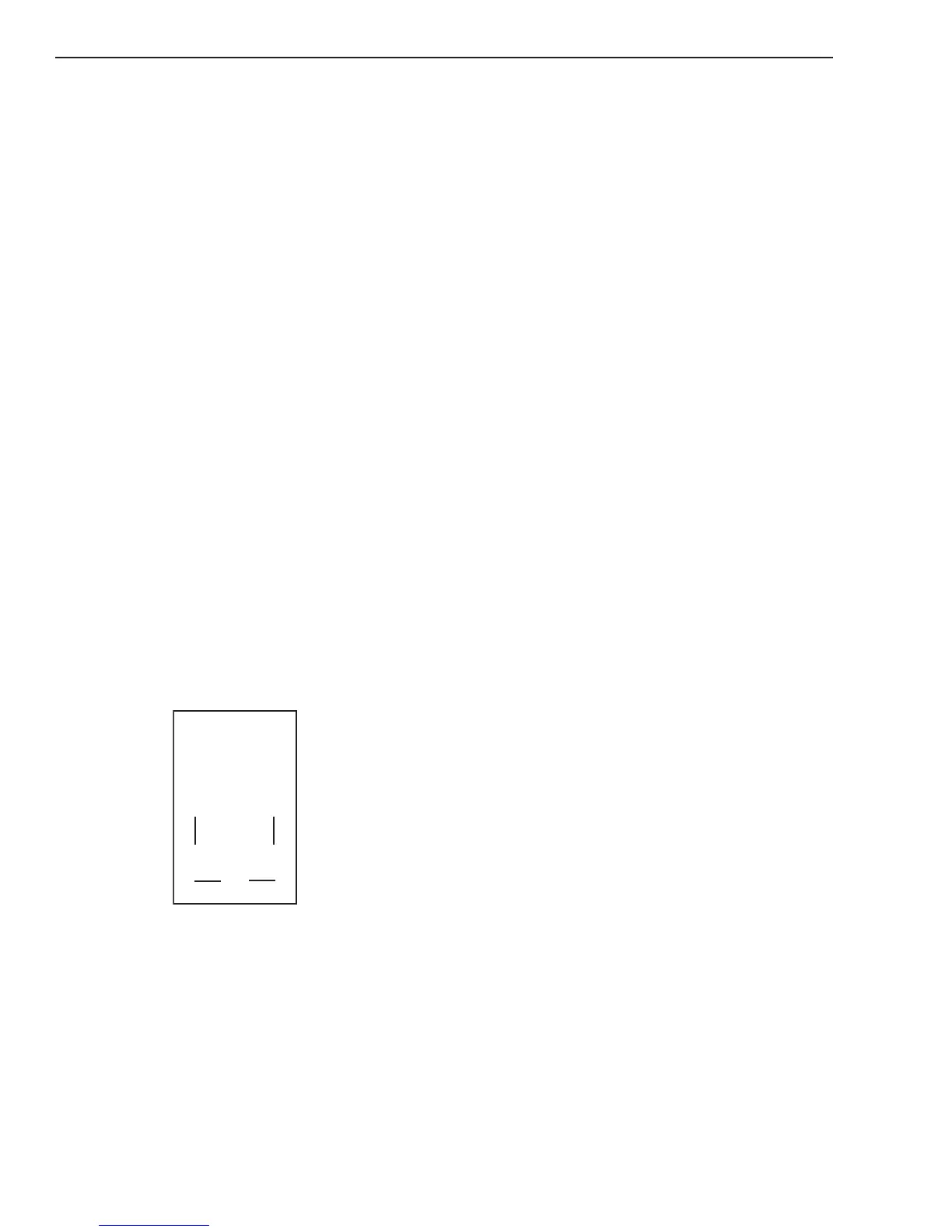
H. ON/OFF Switch (SW1) Replacement
Tools required: T20 Torx Driver
1. Remove the cover per subsection 7.04A
2. Disconnect the wires on the rear of the switch,
noting the location and orientation of each wire
as shown below.
3. Squeeze together the clips on the back of the
switch, then remove the switch through the front
panel.
4. Install the replacement switch by reversing the
above steps.
5. Reinstall the power supply cover
I. Work Cable Replacement
Tools required: T20 Torx Driver
1. Remove the Cover per subsection 7.04A.
2. Disconnect the work cable from the WORK1
terminal on the Main PCB.
3. Squeeze the top and bottom of the Work Cable
Strain Relief and remove from the front panel.
4. Install the replacement Work Cable by reversing
the above steps.
5. Reinstall the power supply cover
7.06 Left Side Internal Parts
Replacement
A. Fan Replacement
Tools required: T20 Torx Driver
Fan MOT1
1. Remove the Cover per subsection 7.04A
2. Unplug J7 connector from Main PCB
3. Carefully feed the fan wires through the center
chassis wire slot.
4. Remove the fan by pushing the fan retaining
clips apart and pulling the fan out of the center
chassis.
5. On the replacement fan(s) note the direction of
air flow as labeled on the fan housing and orient
so fan will blow air into the heatsink.
6. Install replacement fan by reversing the above
steps.
7. Reinstall the power supply cover
Fans MOT2 or MOT3
1. Remove the Cover per subsection 7.04A
2. Unplug corresponding J1 or J2 connector from
the Main PCB.
3. Carefully feed the fan wires through the center
chassis wire slot.
4. Remove the fan by pushing the fan retaining
clips apart and pulling the fan out of the center
chassis.
5. On the replacement fan(s) note the direction of
air flow as labeled on the fan housing and orient
so fan will blow air into the heatsink.
6. Install replacement fan by reversing the above
steps.
7. Reinstall the power supply cover