cutmaster 102
SERVICE 5-20 Manual 0-4998
F. INTERNAL ERROR FAULT INDICATOR AND
90 PSI INDICATOR FLASHING
1. There has been a microprocessor problem.
a) Turn ON/OFF SWITCH to OFF position and
then turn to ON position to clear the error
2. Defective Logic PCB 3.
a) Replace Logic PCB 3.
5.10 CNC Interface Problems
A. Nothing happens when jumper is installed
between J2-3 to J2-4.
1. Defective Automation Interface PCB 4.
a) Measure voltage on PCB4 between J1-6 to J1-8
for 12VDC.
If 12VDC is present replace Automation Interface
PCB 4
2. Defective Main PCB 1.
a) Measure voltage on Main PCB 1 between J1-6
to J1-8 for less than 2VDC.
If voltage is less than 2VDC, replace Main PCB`1.
B. No OK-TO-MOVE signal while cutting.
1. Defective Main PCB`1
a) Measure voltage on PCB4 between J1-1 to J1-3
for 12VDC while cutting.
If 12VDC is present, replace PCB 1
2. Defective Automation Interface PCB 4
a) Measure voltage on PCB 4 between J1-1 to J1-3
for less than 2VDC while cutting.
If voltage is less than 2VDC, replace PCB 4.
C. ARC VOLTS signals are low or not present
1. Defective Automation Interface PCB 4
a) Replace PCB`4
5.11 Test Procedures
A. Main Contactor (W1) Test
1. Check continuity between:
L1 to T1
L2 to T2
L3 to T3
L4 to T4
The contacts should be open – no continuity. If con-
tinuity is found, disconnect J1 from the Main PCB 1
and recheck. If continuity still exists, replace W1. If
disconnecting J1 from Main PCB 1 removes the short,
replace the Main PCB 1.
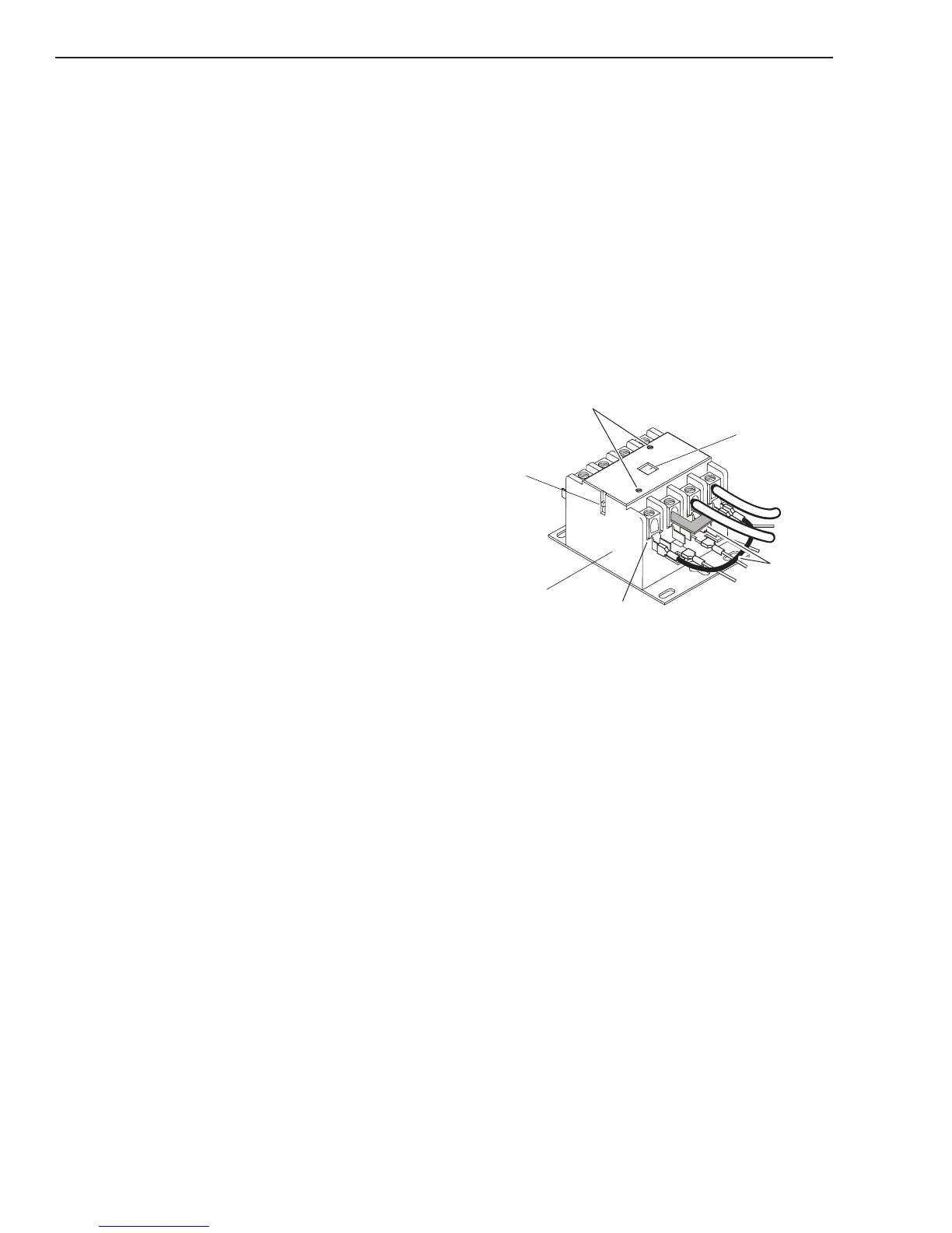
L4
L3
L2
L1
T4
T3
T2
T1
Actuator Arm
Cover Screws
Art # A-08157_AB
Input
Side
CutMaster 52 & 82
W1 contactor wired for 1PH
Main Contactor
Jumpers
Actuator Button
2. Retest continuity between terminals while engag-
ing the contacts manually. This can be done by
pushing down on the recessed actuator button on
the top of W1 or pushing down on the actuator
arm on the side of W1.
L1 to T1
L2 to T2
L3 to T3
L4 to T4
The contacts should be closed – Continuity
3. Visually check W1 contact points. To take the
cover off, remove the two cover screws shown
in the previous illustration. If contacts are stuck
together or show excessive arcing or pitting, re-
place W1.
 Loading...


