cutmaster 102
Manual 0-4998 7-3 PARTS REPLACEMENT
7.05 Front Panel Parts Replacement
Refer to section 6.05 for Front Panel Replacement Parts
and overall detailed drawing.
A. Current Control Potentiometer (A) Knob
Replacement
Tools required: Flat Screw Driver
1. Turn the potentiometer fully clockwise and note
the location of the pointer mark on the knob.
2. Loosen the screw securing the Current Control
Knob to the potentiometer shaft and remove the
knob.
3. Replace the knob on the potentiometer shaft with
the pointer in the same position as noted in step
1.
B. Function Control Switch Knob
Replacement
Tools required: Flat Screw Driver
1. Turn the Function Control Switch until the
pointer on the knob is in the LATCH position.
2. Loosen the screw securing the knob to the switch
shaft and remove the knob.
3. Replace the knob on the switch shaft with the
pointer in the position noted in step 1.
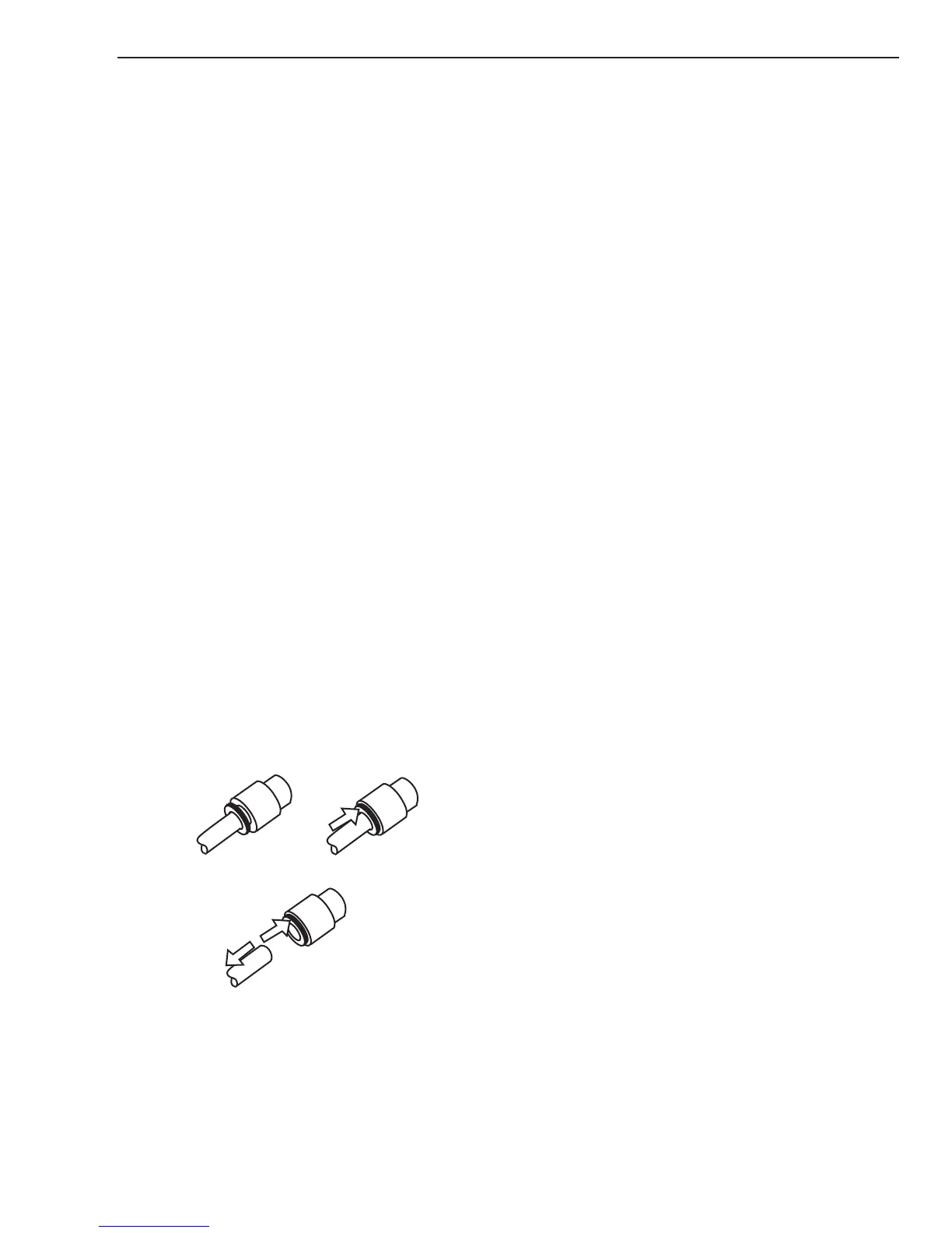
C. Replacing Gas Hoses
Tools required: T20 Torx Driver
1. Remove the cover per subsection 7.04A
2. Push the gas fitting locking ring back. A small
open end wrench works well for this.
3. Pull the hose from the fitting.
4. Replace the hose by pushing the hose back into
the fitting until it fully seats. Check it by pull-
ing on the hose. If done correctly it will not pull
out.
5. Reinstall the power supply cover
D. Air Regulator Replacement
Tools required: T20 Torx Driver, 11/16" Open End
Wrench
1. Remove the cover per subsection 7.04A
2. Remove the two(2) air hoses from the regulator
per subsection 7.05-C
3. Disconnect cable from the Pressure Transducer
4. Pull the Air Regulator adjusting knob from the
shaft.
5. Loosen and remove the locking nut securing the
Air Regulator to the front Panel, then remove the
regulator.
6. Remove the Pressure Transducer from the regu-
lator and install on new regulator using liquid
pipe thread sealant.
6. Install replacement Air Regulator by reversing
the above steps 2-5.
7. Reinstall the power supply cover
E. Pressure Transducer Replacement
Tools required: T20 Torx Driver, 11/16" Open End
Wrench
1. Remove Air Regulator per subsection 7.05D
2. Remove the defective Pressure Transducer from
the regulator and install the new Transducer onto
the Air Regulator.
3. Install the regulator assembly per subsection
7.05D.
4. Reinstall the power supply cover
F. Gas Solenoid Replacement
Tools required: T20 Torx Driver, Flat Screw Driver
1. Remove the cover per subsection 7:04A
2. Disconnect J5 connector from the Main PCB.
3. Remove the air hose from Gas Solenoid per sub-
section 7.05-C
4. The Solenoid utilizes the same type locking fit-
ting as the gas hoses. Using a flat blade screw
driver, push the locking ring towards the Sole-
noid while pulling the Solenoid away from the
ATC.
5. Install the replacement Gas Solenoid by reversing
the above steps
6. Reinstall the power supply cover