CUTMASTER 60i
Manual 0-5436 INTRODUCTION
2T-1
SECTION 2 TORCH:
INTRODUCTION
2T.01 Scope of Manual
This manual contains descriptions, operating instruc-
tions and maintenance procedures for the 1Torch Models
SL60, SL60QD™ and SL100/Mechanized Plasma Cut-
ting Torches. Service of this equipment is restricted to
properly trained personnel; unqualified personnel are
strictly cautioned against attempting repairs or adjust-
ments not covered in this manual, at the risk of voiding
the Warranty.
Read this manual thoroughly. A complete understanding
of the characteristics and capabilities of this equipment
will assure the dependable operation for which it was
designed.
2T.02 General Description
Plasma torches are similar in design to the automotive
spark plug. They consist of negative and positive sec-
tions separated by a center insulator. Inside the torch,
the pilot arc starts in the gap between the negatively
charged electrode and the positively charged tip. Once
the pilot arc has ionized the plasma gas, the superheated
column of gas flows through the small orifice in the torch
tip, which is focused on the metal to be cut.
A single torch lead provides gas from a single source
to be used as both the plasma and secondary gas. The
air flow is divided inside the torch head. Single - gas
operation provides a smaller sized torch and inexpensive
operation.
CAUTION
Torch Leads are flexible but in-
ternal wires can be broken. Do
not exceed a 2" radius bend and
avoid repeated tight bends when
possible.
NOTE!
Refer to Section "2T.05 Introduction to
Plasma", for a more detailed description of
plasma torch operation.
Refer to the Appendix Pages for additional
specifications as related to the Power Sup-
ply used.
2T.03 Specifications
A. Torch Configurations
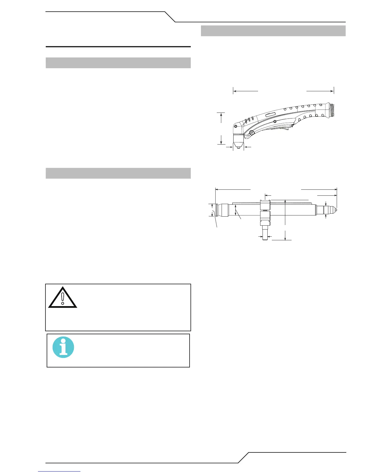
1. Hand/Manual Torch, Model SL60QD™
The hand torch head is at 75° to the torch handle.
The hand torches include a torch handle and torch
trigger assembly.
10.125" (257 mm)
3.75"
1.17" (29 mm)
Art # A-13246
2. Mechanized Torch, Model
The standard machine torch has a positioning
tube with rack & pinch block assembly.
Ar
1.75" /
44.5 mm
1.375" / 35 mm
0.625" /
4.95" / 126 mm
1.175" / 30 mm
9.285" / 236 mm
B. Torch Leads Lengths
Hand Torches are available as follows:
• 20 ft / 6.1 m, with ATC connectors
• 50 ft / 15.2 m, with ATC connectors
Machine Torches are available as follows:
• 5 foot / 1.5 m, with ATC connectors
• 10 foot / 3.05 m, with ATC connectors
• 25 foot / 7.6 m, with ATC connectors
• 50 foot / 15.2 m, with ATC connectors
C. Torch Parts
Starter Cartridge, Electrode, Tip, Shield Cup
D. Parts - In - Place (PIP)
Torch Head has built - in switch
15 VDC circuit rating
 Loading...


