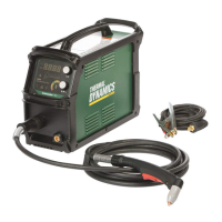
CUTMASTER 60i
OPERATION Manual 0-5436
4-4
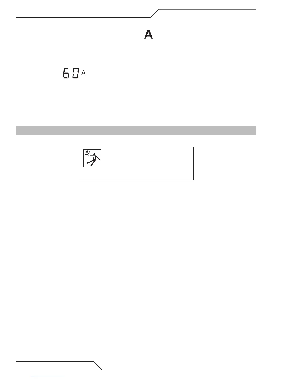
16. Upper Knob - Amp and Mode Selector
Rotate knob to increase or decrease amperage. Indicator is ON when numeric display is showing amper-
age output.
Press and release knob without turning to step through the different Modes.
Factory default: On
Numeric display
17. Torch Quick Disconnect Receptacle
Torch Leads are connected here by aligning the connectors, pressing in and turning locking ring clockwise-to-
the-right to secure. Connection should only be snug with no tools used.
18. Work Lead Dinse type receptacle
Align Dinse type connector on work lead with receptacle, press in and turn clockwise to the right until tight.
4.02 Preparations for Operation
At the start of each operating session:
WARNING
Disconnect primary power at the source
before assembling or disassembling power
supply, torch parts, or torch and leads as-
semblies.
Torch Parts Selection
Check the torch for proper assembly and appropriate torch parts. The torch parts must correspond with the
type of operation, and with the amperage output of this Power Supply (60 amps maximum). Refer to Section
4T.07 and following for torch parts selection.
Torch Connection
Check that the torch is properly connected. Only Thermal Dynamics models SL60, SL60QD™ / Manual or
SL100 / Mechanical Torches may be connected to this Power Supply. See Section 3T of this manual.
Check Primary Input Power Source
1. Check the power source for proper input voltage. Make sure the input power source meets the power re-
quirements for the unit per Section 2, Specifications.
2. Connect the input power cable (or close the main disconnect switch) to supply power to the system.
Air Source
Ensure source meets requirements (refer to Section 2). Check connections and turn air supply ON.
 Loading...


