CUTMASTER 60i
OPERATION Manual 0-5436
4T-6
NOTE!
The gas preflow and postflow are a char-
acteristic of the power supply and not a
function of the torch.
When the shield cup is properly installed,
there is a slight gap between the shield cup
and the torch handle. Gas vents through
this gap as part of normal operation. Do
not attempt to force the shield cup to close
this gap. Forcing the shield cup against
the torch head or torch handle can damage
components.
7. Clean spatter and scale from the shield cup and
the tip as soon as possible. Spraying the shield
cup in anti - spatter compound will minimize the
amount of scale which adheres to it.
Cutting speed depends on material, thickness, and the
operator’s ability to accurately follow the desired cut
line. The following factors may have an impact on sys-
tem performance:
• Torch parts wear
• Air quality
• Line voltage fluctuations
• Torch standoff height
• Proper work cable connection
4T.05 Gouging
WARNING
Be sure the operator is equipped with
proper gloves, clothing, eye and ear protec-
tion and that all safety precautions at the
front of this manual have been followed.
Make sure no part of the operator’s body
comes in contact with the workpiece when
the torch is activated.
Disconnect primary power to the system
before disassembling the torch, leads, or
power supply.
CAUTION
Sparks from plasma gouging can cause
damage to coated, painted or other sur-
faces such as glass, plastic, and metal.
Check torch parts. The torch parts must
correspond with the type of operation. Refer
to Section 4T.07, Torch Parts Selection.
Gouging Parameters
Gouging performance depends on parameters
such as torch travel speed, current level, lead angle
(the angle between the torch and workpiece), and
the distance between the torch tip and workpiece
(standoff).
!
CAUTION
Touching the torch tip or shield cup to the
work surface will cause excessive parts
wear.
Torch Travel Speed
NOTE!
Refer to Appendix Pages for additional infor-
mation as related to the Power Supply used.
Optimum torch travel speed is dependent on current
setting, lead angle, and mode of operation (hand or
machine torch).
Current Setting
Current settings depend on torch travel speed,
mode of operation (hand or machine torch), and the
amount of material to be removed.
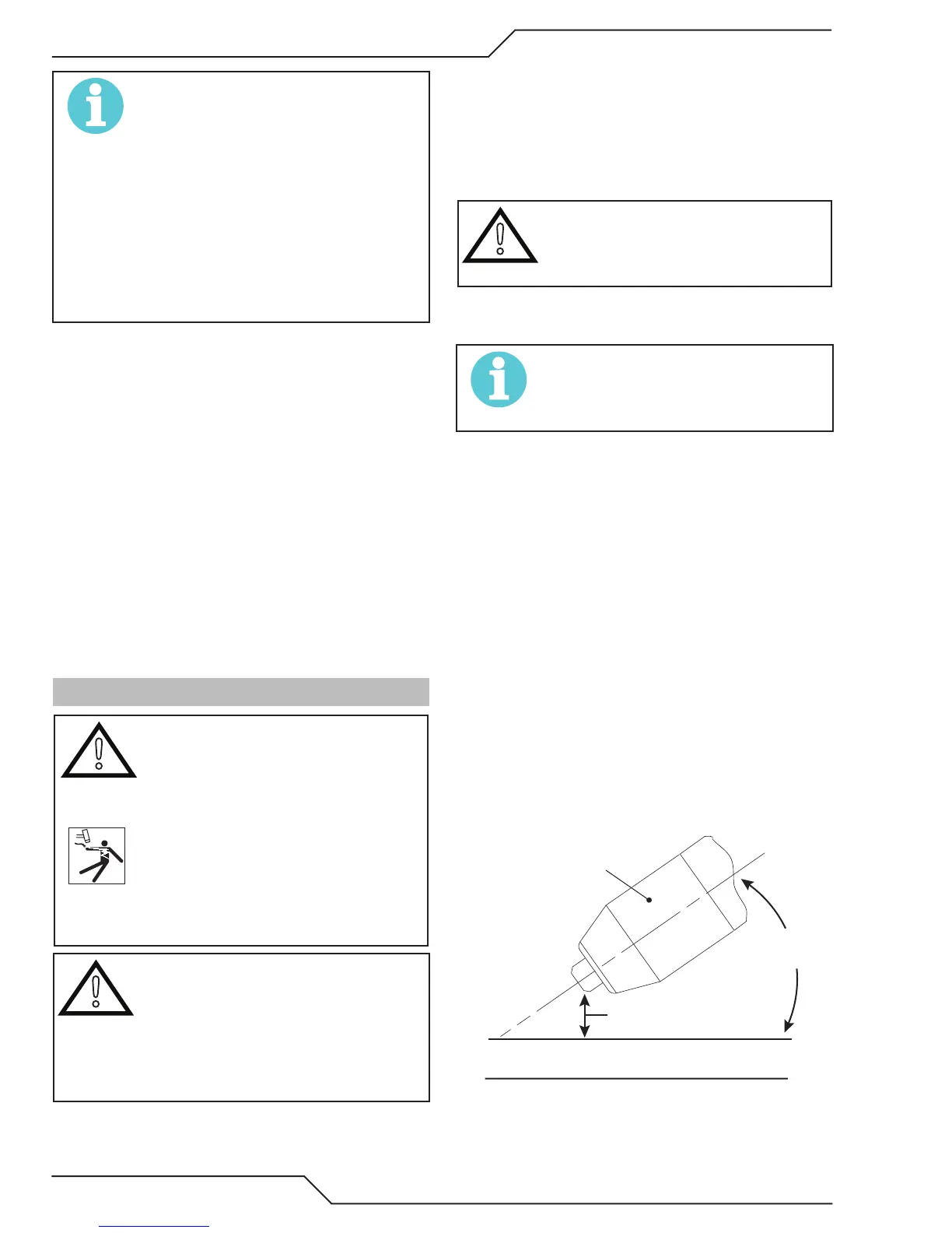
Lead Angle
The angle between the torch and workpiece depends
on the output current setting and torch travel speed.
The recommended lead angle is 35°. At a lead angle
greater than 45° the molten metal will not be blown
out of the gouge and may be blown back onto the
torch. If the lead angle is too small (less than 35°),
less material may be removed, requiring more pass-
es. In some applications, such as removing welds
or working with light metal, this may be desirable.
35°
Workpiece
Torch Head
Standoff Height
A-00941_AB
Gouging Angle and Standoff Distance
 Loading...


