CUTMASTER 60i
INSTALLATION Manual 0-5436
3-4
3.06 Gas Connections
Connecting Gas Supply to Unit
The connection is the same for compressed air or high pressure cylinders. Refer to the following two subsections
if an optional air line filter is to be installed.
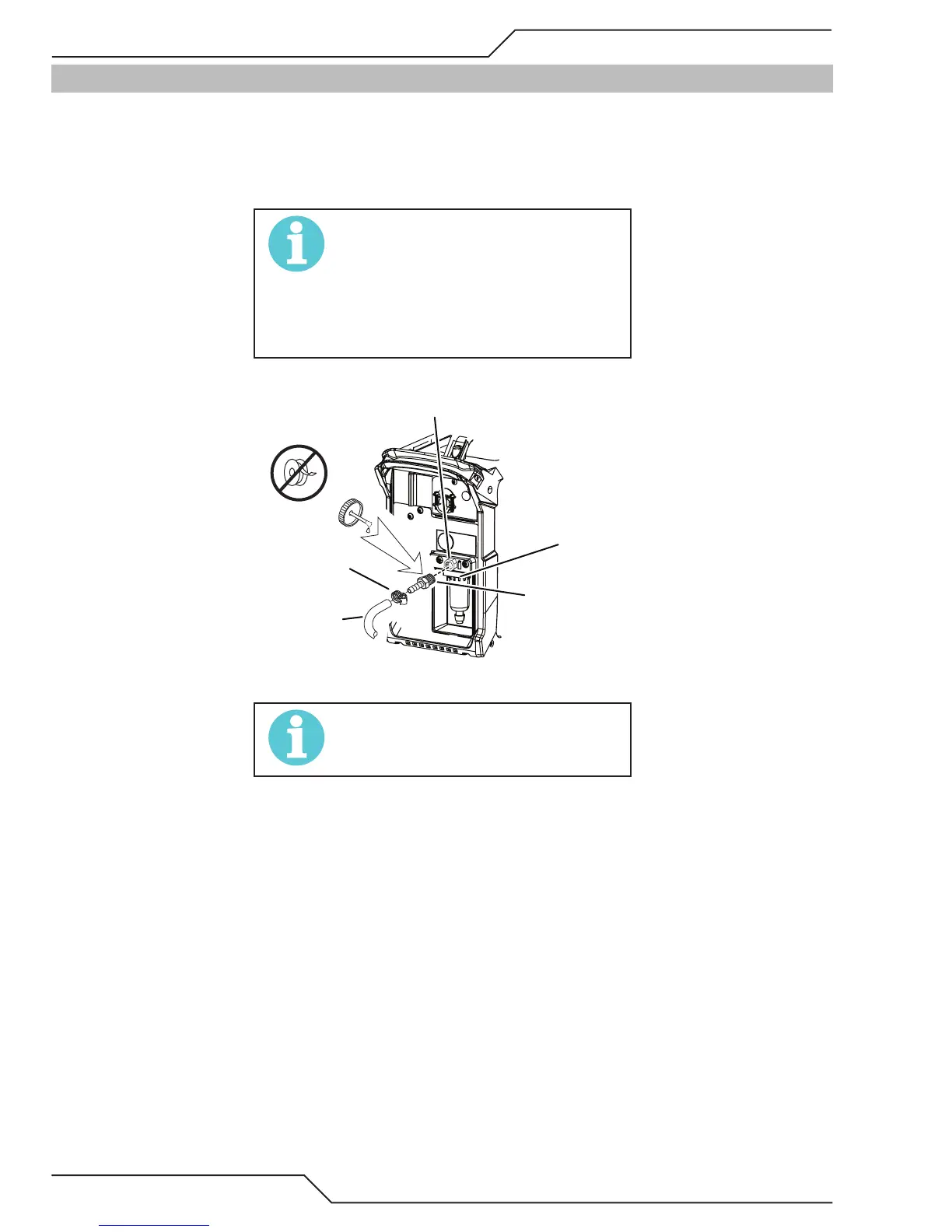
1. Connect the air line to the inlet port. The illustration shows typical fittings as an example.
NOTE!
For a secure seal, apply thread sealant to
the fitting threads, according to manufac-
turer’s instructions. Do not use Teflon tape
as a thread sealer, as small particles of the
tape may break off and block the small air
passages in the torch.
3/8 barb to
1/4 NPT”
(6mm) Fitting
Filter
Assembly
1/4 NPT Inlet Port
Hose Clamp
Gas Supply
Hose
Air Connection to Inlet Port
NOTE!
Filter replacement part numbers can be
found in Section 6 of this manual
 Loading...


