CUTMASTER 60i
OPERATION Manual 0-5436
4T-14
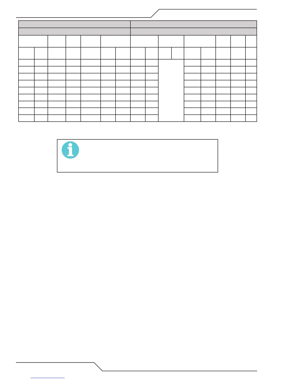
CutMaster® 60i With Shielded Tip Type Material: Aluminum
Type Plasma Gas: Air Type Secondary Gas: Single Gas Torch
Thickness Tip Output Amperage Speed (Per
Minute)
Standoff Plasma Gas
Pressure*
Flow (SCFH) Pierce Pierce
Height
Inches mm (Cat.
No.)
Volts
(VDC)
(Amps) Inches Meters Inches mm psi bar Plasma Total** Delay
(Sec)
Inches mm
0.060 1.5 9-8210 105 60 350 8.89 0.13 3.2
Set to the
central
region on
the pressure
dial. This is
illuminated
green when
selected.
90 245 0.00 0.20 5.1
0.075 1.9 9-8210 110 60 350 8.89 0.13 3.2 90 245 0.10 0.20 5.1
0.120 3.0 9-8210 110 60 275 6.99 0.13 3.2 90 245 0.10 0.20 5.1
0.188 3.4 9-8210 122 60 140 3.56 0.13 3.2 90 245 0.20 0.20 5.1
0.250 6.4 9-8210 134 60 80 2.03 0.19 4.8 90 245 0.30 0.20 5.1
0.375 9.5 9-8210 140 60 45 1.14 0.19 4.8 90 245 0.50 0.20 5.1
0.500 12.7 9-8210 144 60 26 0.66 0.19 4.8 90 245 0.80 0.20 5.1
0.625 15.9 9-8210 145 60 19 0.48 0.19 4.8 90 245 NR NR NR
0.750 19.1 9-8210 150 60 15 0.38 0.19 4.8 90 245 NR NR NR
NOTE!
* Gas pressure shown is for torches with leads up to 25’ / 7.6 m
long. For 50’ / 15.2 m leads, refer to Section “Set Operating Pres-
sure” on page <?>.
** Total flow rate includes plasma and secondary gas flow.
 Loading...


