cutmaster 82
PARTS LIST 6-4 Manual 0-4980
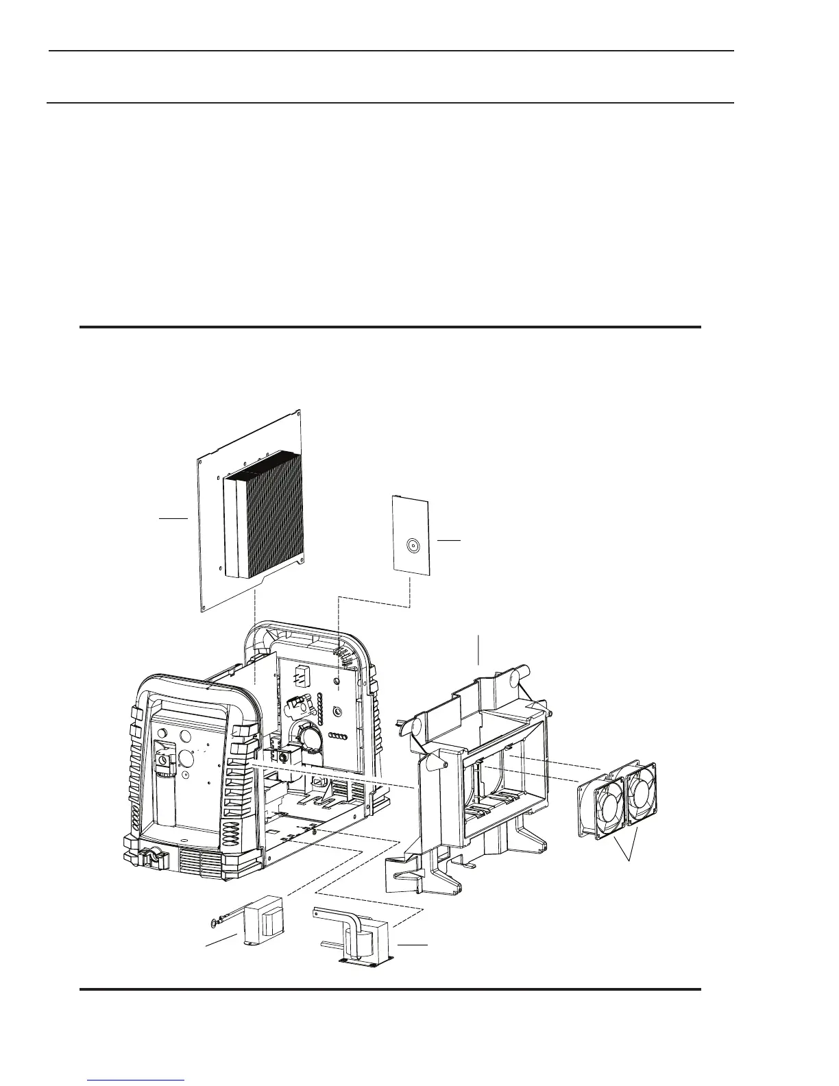
6.06 Left Side Replacement Parts
Item # Qty Description Ref Catalog #
1 1 Main PCB Assembly PCB1 9-0125
2 1 Logic PCB PCB3 9-0107*
3 1 Center Chassis Molded Plastic 9-0102
4 1 Fan, MOT1,MOT2 9-0104
5 1 Transformer, Main Non 600V T1 9-0199
5 1 Transformer, Main 600V Only T1 9-0170
6 1 Inductor, Output L1 9-0105
Not Shown:
1 Power Cable Strain Relief, for all units 9-0111
1 Input Power Cable 230 V with plug, 9-8596
1 Input Power Cable 460/600V 9-8593
1 Hi/Lo voltage selection switch 9-0110
NOTE:
*9-0107 Logic PCB, If the serial number of the power supply is prior to #05078755 then kit number 9-0201 will
be needed to replace not only the Logic PCB (9-0107) but the regulator (9-0115) as well. Another way to tell if
the kit is needed is to see if the regulator has a small diameter tube coming out of the bottom fitting. If there is a
transducer and wire harness instead of the tube, the kit is not needed.
NOTE
Illustration may vary slightly from unit.