cutmaster 82
INSTALLATION 3-2 Manual 0-4980
3.03 Primary Input Power Connections
CAUTION
Check your power source for correct voltage before plugging in or connecting the unit. Check the Voltage Selector
at the rear of the unit for correct setting before plugging in or connecting the unit. The primary power source, fuse,
and any extension cords used must conform to local electrical code and the recommended circuit protection and
wiring requirements as specified in Section 2.
Most units are shipped from the factory with a 230Volt input power cable wired to the input contactor in
the single - phase conguration. The following illustrations and directions are for changing that con-
guration to a different voltage and or to three - phase operation or back again if a change had already
been made.
Art # A-07984_AB
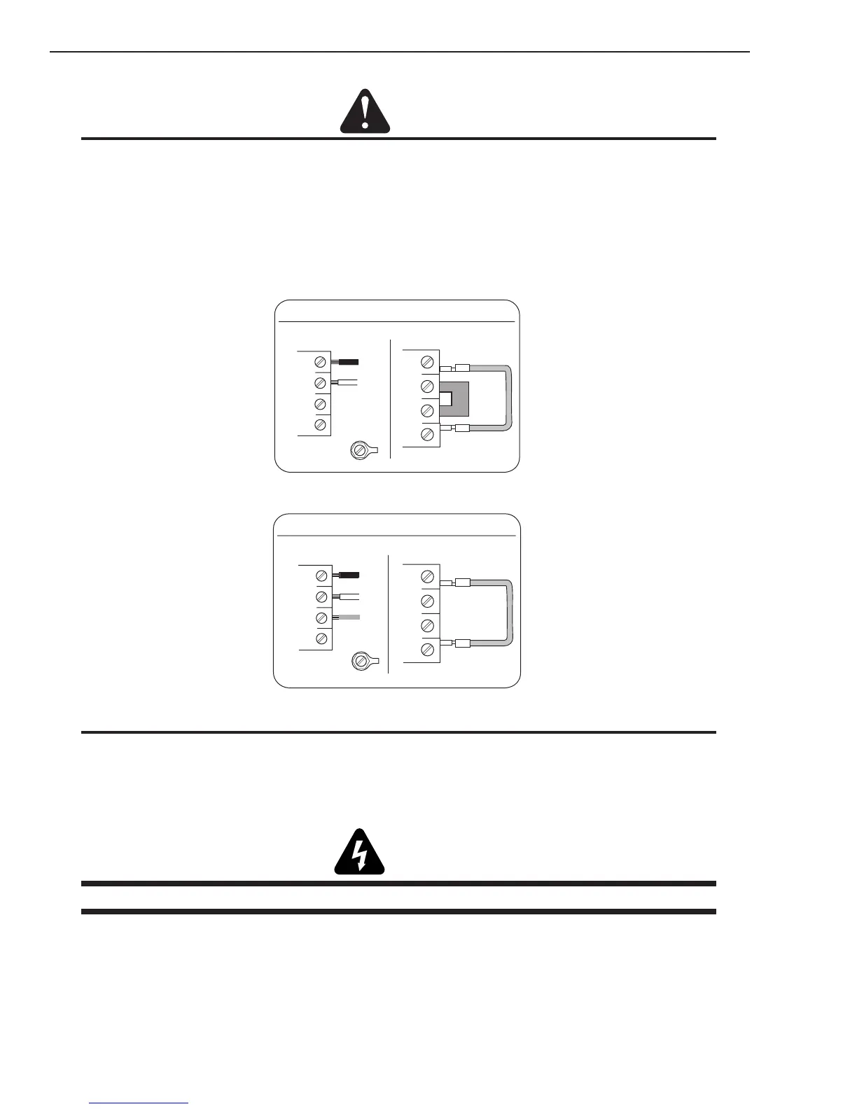
Single-Phase (1ø) and Jumper Settings
L1
L2
L3
L4
Jumper L1 -L4
Jumper
L2-L3
L1
L2
L3
GND
L4
Single Phase Input Power Wiring
Art # A-07983_AB
Three-Phase (3ø) and Jumper Settings
L1
L2
L3
L4
Jumper L1 -L4
L1
L2
L3
GND
L4
Store copper jumper in spare parts box
Three Phase Input Power Wiring
NOTE
There is only one jumper setting that changes between the single and three phase settings. To change from single
phase to three phase, the jumper connected to L2 needs to be removed and placed on the other L3 connection so both
ends of the jumper are attached to the same electrical point. See previous illustrations.
A. Connections to Single Phase Input Power
WARNING
Disconnect input power from the power supply and input cable before attempting this procedure.
These instructions are for changing the input power and or cable on the 208/230, 400, 460 VAC Power
Supply to Single - Phase input power.
1. Remove the Power Supply cover per instructions found in section 5.
2. Disconnect the original input power cable from the main input contactor and the chassis ground
connection.
3. Loosen the through - hole protector on the back panel of the power supply. Pull the original
power cable out of the power supply.