cutmaster 82
Manual 0-4980 7-5 PARTS REPLACEMENT
13. Remove the two screws securing the Main Trans-
former to the base.
14. Remove the Main Transformer, carefully guiding
all its wires through from the right side of the
unit.
15. Install replacement Transformer by reversing the
above steps.
16. Reinstall the power supply cover
C. Output Inductor (L1)
Tools required: T20 Torx Driver, ½” Nut Driver
1. Remove the Cover per subsection 7.04A
2. Remove the Tube Handle per subsection 7.04C
3. Remove the two large and one small gas hoses
per subsection 7.05-C
4. Remove the Gas Solenoid per subsection 7.05-E
5. Disconnect J2 & J3 connectors from Main PCB.
6. Disconnect Output Inductor wire from terminal
Choke1 on the Main PCB.
7. Disconnect Output inductor wire from ATC con-
nector.
8. Remove the two screws securing the Center
Chassis to the base.
9. Loosen the two screws on the Input Power Cable
strain relief.
10. Disengage the Rear panel from the base per sec-
tion 7.04D.
11. Guide the rear panel back six (6) inches away
from the base.
12. Guide the Center Chassis towards the center of
the base to disengage the bottom locking tabs
securing the Chassis to the base.
13. Carefully guide the Center Chassis up far enough
to lay the Chassis down towards the right side
of the unit.
14. Remove the two screws securing the Output
Inductor to the base.
15. Remove the Output Inductor, carefully guid-
ing its wires through from the right side of the
unit.
16. Install replacement Output Inductor by reversing
the above steps.
17. Reinstall the power supply cover.
7.07 Rear Panel Parts Replacement
A. Filter Element Assembly Replacement
The Filter Element Assembly is in the rear panel. For
better system performance, the filter element should be
checked per the Maintenance Schedule (Subsection 5.02),
and either cleaned or replaced.
1. Remove power from the power supply; turn off
the gas supply and bleed down the system.
2. Remove the system cover. See "A Cover Re-
moval" in this section.
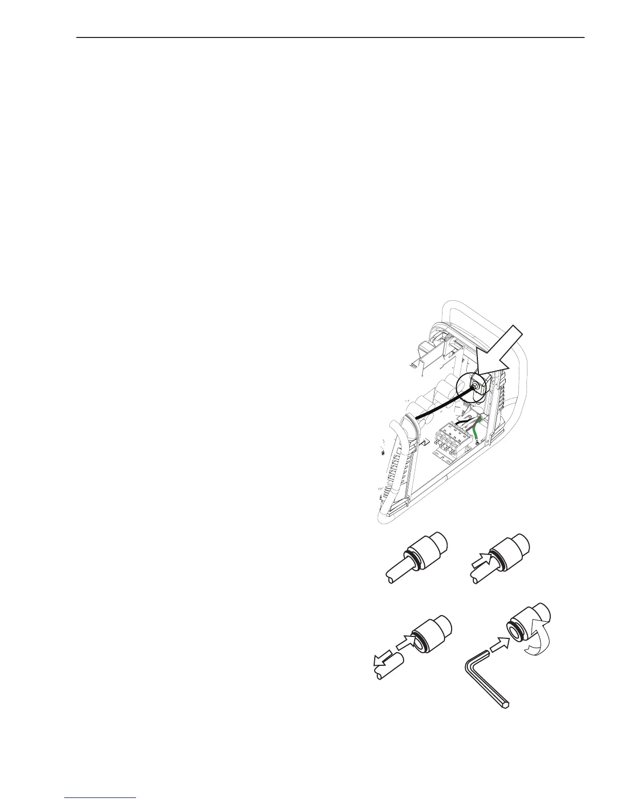
3. Locate the internal air line and the fitting from
the filter assembly. Number 1 in the following
illustration.
4. Hold a wrench or similar tool against the locking
ring on the filter assembly fitting, then pull on
the hose to release it. (Numbers 2 and 3 in the
following illustration).
5. Remove the fitting from the filter element as-
sembly by inserting a 6 mm hex wrench into