cutmaster 82
SERVICE 5-12 Manual 0-4980
5.08 Main Input and Internal Power
Problems
A. Primary input line fuse blows as soon as
primary disconnect is closed.
1. Primary input cable installed incorrectly.
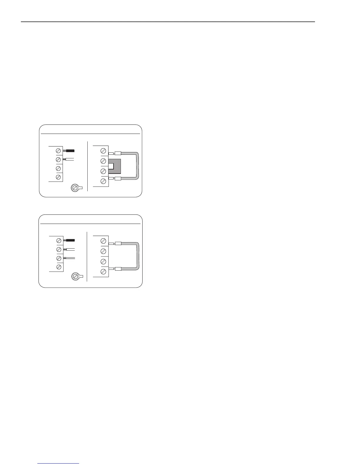
a) Check wiring of primary power cable to the
contactor. See illustration below.
2. W1 jumpers installed incorrectly
a) Check jumper installation for correct phase
being used.
Art # A-07984_AB
Single-Phase (1ø) and Jumper Settings
L1
L2
L3
L4
Jumper L1 -L4
Jumper
L2-L3
L1
L2
L3
GND
L4
Single Phase Input Power Wiring
Art # A-07983_AB
Three-Phase (3ø) and Jumper Settings
L1
L2
L3
L4
Jumper L1 -L4
L1
L2
L3
GND
L4
Store copper jumper in spare parts box
Three Phase Input Power Wiring
3 W1 contactor points are stuck closed
a) Check per section 5.11A
4. Primary plug not wired correctly.
a) Check manufacturer's plug installation instruc-
tions.
5. Primary input cable is defective.
a) Check cable for shorts.
B. Primary line fuses blow immediately after
ON/OFF SWITCH (SW1) is turned to ON
position.
1. Shorted Input Diode Module
a) Check per section 5.11B
2. Shorted Input Capacitor Pcb
a) Check per section 5.11C
C. Gas flows with ON/OFF SWITCH in OFF
position
1. Foreign debris has lodged in gas solenoid.
a) Replace gas solenoid. This is a problem caused
by improperly filtered air supply. Customer
needs to add filtration to air supply prior to
unit inlet.
D. All front panel indicators are off, fans
do not run. Main Contactor W1 does not
close.
1. Primary power not connected.
a) Check that cable is connected to primary
power.
2. Primary line fuse/breaker is blown/tripped.
a) Replace fuse or reset breaker.
3. Defective ON/OFF SWITCH
a) Check continuity
4. Defective Main Pcb
a) Measure Main Pcb power supply voltages at
the following test points
GND1 to +12V = 12VDC
GND1 to +48V = 48 VDC
Replace Main Pcb if not correct
5. Defective Ribbon Cable
a) Check continuity
6. Defective Logic
a) Replace Logic Pcb