INTRODUCTION & DESCRIPTION 2-2 Manual 0-2815
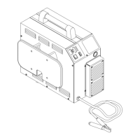
H. Torch Dimensions
A-02804
14.1 in
(358 mm)
0.62 in
(15.2 mm)
0.75 in
(19 mm)
5.1 in
(129.5 mm)
1.1 in
(28 mm)
1.4 in
(35.6 mm)
13.5 in (343 mm) Max
3.7 in (94 mm) Min
Figure 2-2 Torch Dimensions
2.04 Options And Accessories
These items can be used to customize a standard system
for a particular application or to further enhance perfor-
mance (refer to Section 6 for ordering information).
• Spare Parts Kits - Various kits containing replace-
ment front-end torch parts for various applications.
• 1-3/8" Metal Mounting Tube w/Rack & Pinion As-
sembly
• Pinion Assembly
• Computer Control (CNC) Cable 25 Ft (7.6 m) or 50 Ft
(15.2 m)
2.05 Introduction to Plasma
A. Plasma Gas Flow
Plasma is defined as a gas which has been heated to
an extremely high temperature and ionized so that it
becomes electrically conductive. The plasma arc cut-
ting and gouging process use this plasma to transfer
an electrical arc to the workpiece. The metal to be cut
or removed is melted by the heat of the arc and then
blown away.
While the goal of plasma arc cutting is separation of
the material, plasma arc gouging is used to remove
metals to a controlled depth and width.
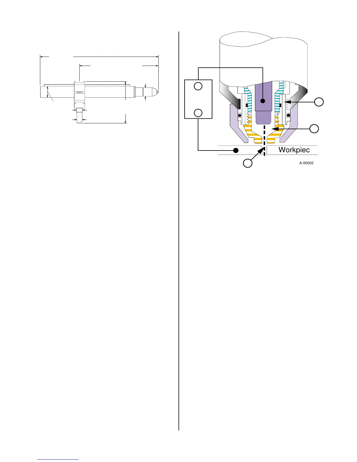
In a Thermal Arc Plasma Cutting Torch a cool gas
such as air or nitrogen (N2) enters Zone B (refer to
Figure 2-3), where a pilot arc between the electrode
and the torch tip heats and ionizes the gas. The main
cutting arc then transfers to the workpiece through
the column of plasma gas in Zone C.
A-00002
Workpiece
Power
Supply
+
_
C
B
A
Figure 2-3 Typical Torch Head Detail
By forcing the plasma gas and electric arc through a
small orifice, the torch delivers a high concentration
of heat to a small area. The stiff, constricted plasma
arc is shown in Zone C (Figure 2-3). Direct current
(DC) straight polarity is used for plasma cutting, as
shown in the illustration.
Zone A (Figure 2-3) is used as a secondary gas that
cools the torch. This gas assists the high velocity
plasma gas in blowing the molten metal out of the cut
allowing for a fast, slag-free cut.
B. Gas Distribution
The single gas used is internally split into plasma
and secondary gases.
The plasma gas flows into the torch through the nega-
tive lead, through the gas distributor, around the elec-
trode, and out through the tip orifice.
The secondary gas flows down around the outside of
the torch gas distributor, and out between the tip and
shield cup around the plasma arc.
C. Pilot Arc
When the torch is started a pilot arc is established
between the electrode and cutting tip. This pilot arc
creates a path for the main arc to transfer to the work.
D. Capacitive Discharge
Because direct current (DC) alone is not sufficient to
strike and maintain the pilot arc, capacitive discharge
is also used. The high voltage jumps between the tip
and electrode with the DC following.
 Loading...