Manual 0-2815 3-1 INSTALLATION PROCEDURES
SECTION 3:
INSTALLATION
PROCEDURES
3.01 Introduction
This section describes installation of the Torch. These
instructions apply to the Torch and Leads Assemblies
only; installation procedures for the Power Supply, Op-
tions and Accessories are given in Manuals specifically
provided for those parts.
The complete installation consists of:
• Site Selection
• Unpacking
• Setting Up Torch
• Connecting Torch
• Gas Connection
3.02 Site Location
Select a clean, dry location with good ventilation and ad-
equate working space around all components.
Review the safety precautions in the front of this manual
to be sure that the location meets all safety requirements.
3.03 Unpacking
Each component of the system is packaged and protected
with a carton and packing material to prevent damage
during shipping.
1. Unpack each item and remove all packing material.
2. Locate the packing list(s) and use the list to identify
and account for each item.
3. Inspect each item for possible shipping damage. If
damage is evident, contact your distributor and/or
shipping company before proceeding with system
installation.
3.04 Setting Up Machine Torch
WARNING
Disconnect primary power at the source before dis-
assembling the torch or torch leads.
The standard machine torch includes a fiberglass posi-
tioning tube with rack and pinch block assembly. A metal
mounting tube with rack & pinion assembly or the pin-
ion assembly only are available as options.
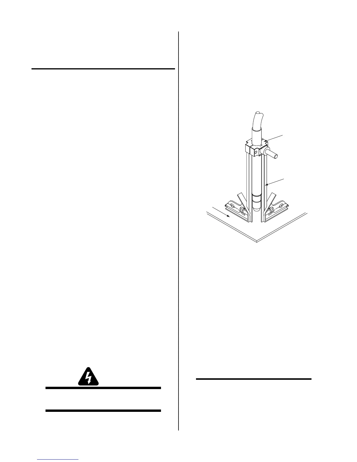
1. Mount the torch assembly on the cutting table.
2. To obtain a clean vertical cut, use a square to align
the torch perpendicular to the surface of the
workpiece.
A-02585
Workpiece
Square
Pinch Block
Assembly
Figure 3-1 Machine Torch Set-Up
3. The proper torch parts (shield cup, tip, gas dis-
tributor, and electrode) must be installed for the
type of operation. Refer to Section 4.04, Torch
Parts Selection for more information.
3.05 Connecting Torch
The instructions for connecting the Torch Leads to the
Automated Power Supply.
The Torch Leads must be properly installed to the Power
Supply for proper operation. If the torch leads were not
factory-installed, make all torch connections to the Torch
Bulkhead Panel.
NOTE
Equipment ordered as a system will have the Torch
factory connected to the Power Supply.
1. Remove the retaining nut from the Strain Relief.
 Loading...