INSTALLATION PROCEDURES 3-2 Manual 0-2815
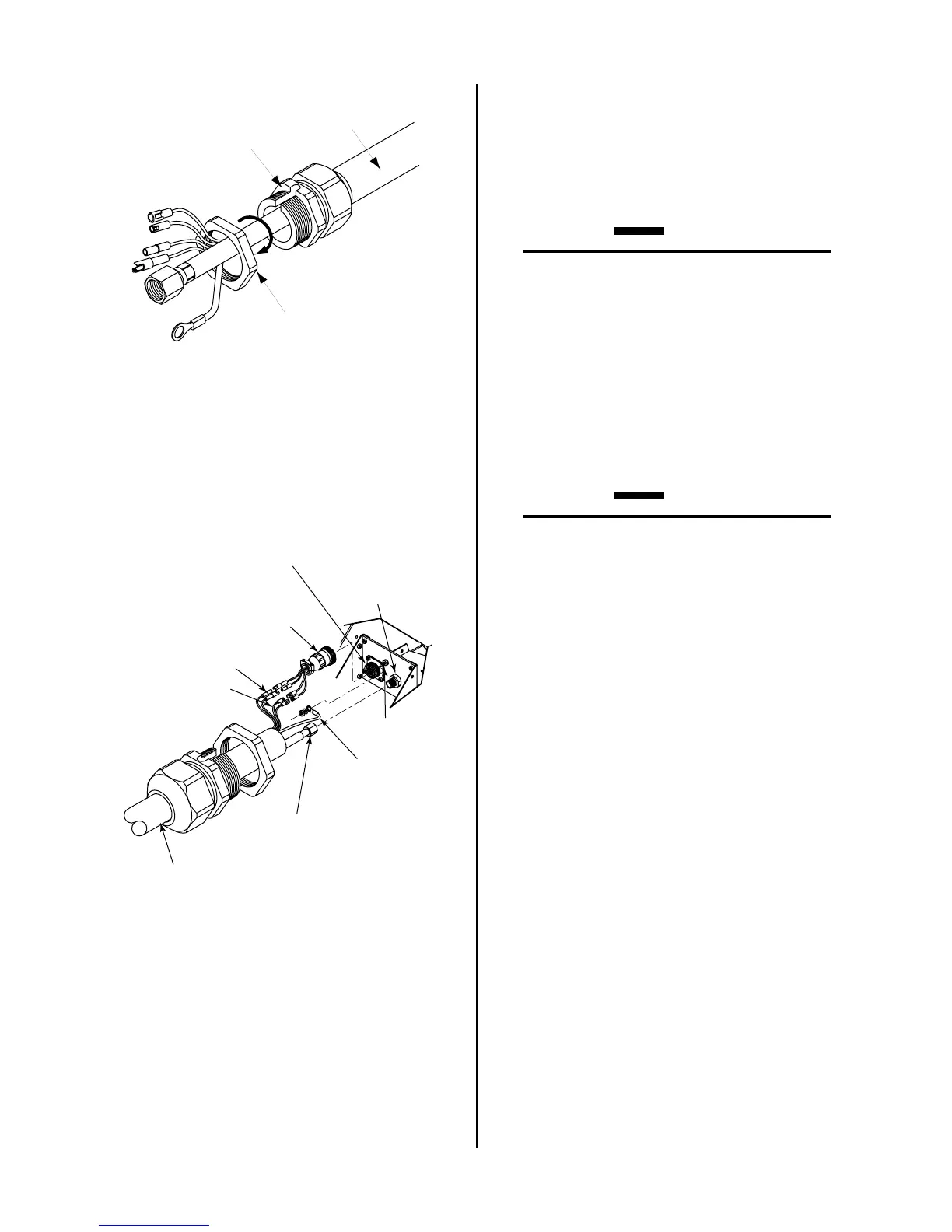
Strain Relief
Nut
Strain Relief
Torch Leads
Assembly
A-02826
Figure 3-2 Strain Relief Nut Removal
2. Feed the torch lead ends and the Strain Relief into
the hole in the unit.
3. Secure the Strain Relief with the retaining nut re-
moved earlier.
Adapter
(Supplied With
Power Supply)
Pilot Lead
Torch Lead
Assembly
Negative/Plasma
Lead
Adapter Connector
Pilot Lead
Stud
Negative/Plasma
Lead Connection
A-02831
Control (PIP) Circuit
Connectors
Shield Connectors
Figure 3-3 Torch Lead Connections
4. Connect the torch Negative/Plasma Lead to the
bulkhead connection inside the Power Supply.
5. Connect the PIP and Shield Cables to the mating
connectors on the Adapter supplied on the Power
Supply.
6. Remove the top nut and washer from the Pilot
Stud.
7. Place the lug on the Pilot Control Wire onto the
stud and secure with the nut and washer removed
in the above Step.
8. Tighten the Strain Relief onto the Torch Leads.
9. Check the torch for proper parts assembly.
CAUTION
The torch parts must correspond with the type of
operation. Refer to Section 4.04, Torch Parts Se-
lection.
3.06 Gas Connection
A. Connection
Connect the gas , compressed air or nitrogen (N2)
only, to the Power Supply as described in the Manual
supplied with the Power Supply.
CAUTION
Air supply must be free of oil, moisture, and other
contaminants. Excessive oil and moisture may
cause double-arcing, rapid tip wear, or even com-
plete torch failure. Contaminants may cause poor
cutting performance and rapid electrode wear.
B. Checking Air Quality
To test the quality of air, place a welding filter lens in
front of the torch and turn on the gas. Any oil or
moisture in the air will be visible on the lens. Do not
initiate an arc!
C. Filtering
An in-line pneumatic dryer/evaporator type air fil-
ter, capable of filtering to at least 5 microns, is required
when using air from a compressor. This type filter
will insure that moisture, oil, dirt, chips, rust particles,
and other contaminants from the supply hose do not
enter the torch. For highly automated applications,
a refrigerated drier may be used.
 Loading...