Chapter 3 | Replacing parts
7. Attach a cable router to the end of each of the cables before removing to allow you to
more easily replace the new cables.
8. Remove the load cell cables from the summing block if it is a standalone
unit. Alternatively, remove the load cell cables from the connector if it is a
controller system.
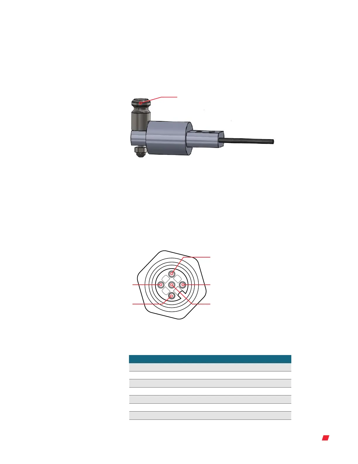
9. Remove the load cell (Figure 3.41).
Load cell knuckle
Figure 3.41. Removed load cell.
3.6.3. Replacement procedures
Rewiring the load cells for 50 and 500 L vessels with a controller
To connect the new load cell to a controller you will need to rewire the load cell cable to
a 5-pin connector.
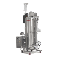
1. Use the schematic and Table 3.4 to wire each wire from the load cell cable to the
5-pin connector (Figure 3.42).
Figure 3.42. Wiring diagram showing connections
from the load cell cables to the 5-pin connector.
3
2
51
4
Table 3.4. 5-pin connector description.
Connector pin Wire colors
Connector pin 1 White (SIG –) Red (SIG –)
Connector pin 2 Green (EXC +) Green (EXC +)
Connector pin 2 Blue (SENSE +) Yellow (SENSE+)
Connector pin 3 Red (SIG +) White (SIG +)
Connector pin 4 Black (EXC –) Black (EXC –)
Connector pin 4 Brown (SENSE –) Blue (SENSE –)
Connector pin 5 Yellow (SHIELD) Yellow-long (SHIELD)
Note: If using a 6-wire load cell, connect “Sense +” to “Excitation +” and “Sense –” to “Excitation –.”
Thermo Scientific 29DynaDrive S.U.B. Service Guide





 To Next Page