Chapter 3 | Replacing parts
3.7.3. Replacement procedures
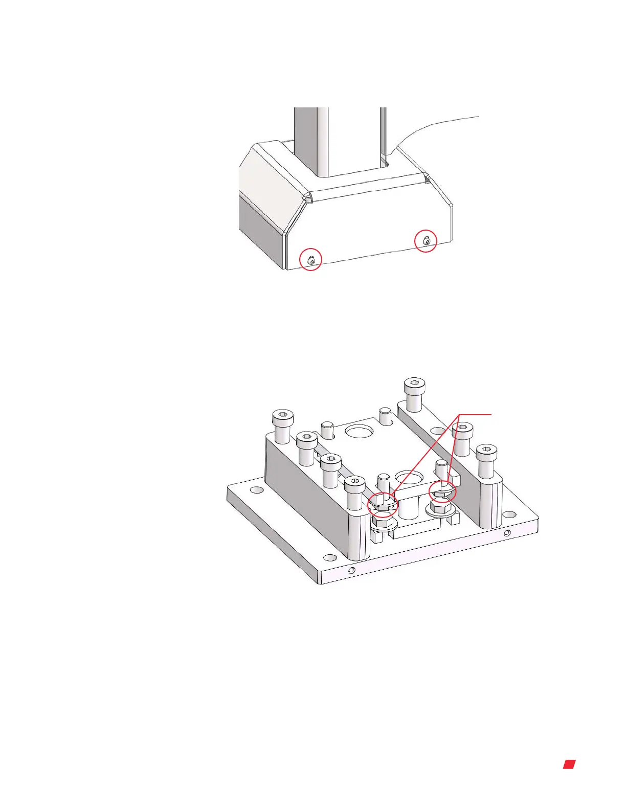
1. Using a 5/32 in. Allen wrench, remove each foot cover by removing the four bolts
(two on each side) (Figure 3.59).
Figure 3.59. Two bolts on the foot cover.
2. Use a hydraulic lift to raise the 3,000 or 5,000 L DynaDrive unit by 1 mm.
3. Once raised, remove the four bolts in the center of each load cell with a crescent
wrench (Figure 3.60).
Figure 3.60. Four bolts in the center of the load cell.
Middle bolts in
load cell
4. Slide out the load cell towards you and replace with a new load cell.
5. Replace the four bolts holding the load cell in place (refer to Figure 3.60).
6. Use a hydraulic lift to lower the 3,000 or 5,000 L DynaDrive unit.
7. Using a 5/32 in. Allen wrench, replace each foot cover by replacing the four bolts
(refer to Figure 3.59).
Refer to the steps in section 3.7. 2 to re-wire the load cell cables back into the
DynaDrive unit.
Thermo Scientific 37DynaDrive S.U.B. Service Guide





 To Next Page