Chapter 3 | Replacing parts
SHLD
-SIG
-EXC
+SIG
+EXC
LC3
SHIELD
-SIG
-SEN
-EXC
+SIG
+SEN
+EXC
INPUT
SHIELD
-SIG
-SEN
-EXC
+SIG
+SEN
+EXC
AUX
SHLD
-SIG
-EXC
+SIG
+EXC
LC1
SHLD
-SIG
-EXC
+SIG
+EXC
LC2
SHLD
-SIG
-EXC
+SIG
+EXC
LC4
TRN1
SUM BLOCK
1
WT
2
BN
3
GN
4
YL
5
GY
6
PK
7
BU
8
RD
CN37
EXC+
PK
SIG+
BN
SHIELD
CLEAR
SIG-
WT
EXC-
GY
LOAD CELL
EXC+
PK
SIG+
BN
SHIELD
CLEAR
SIG-
WT
EXC-
GY
LOAD CELL
EXC+
PK
SIG+
BN
SHIELD
CLEAR
SIG-
WT
EXC-
GY
LOAD CELL
EXC+
PK
SIG+
BN
SHIELD
CLEAR
SIG-
WT
EXC-
GY
LOAD CELL
CN37-1/TN1--EXC
CN37-2/TN1--SEN
CN37-3/TN1--SIG
CN37-4/TN1-SHLD
CN37-5/TN1-+SIG
CN37-6/TN1-+SEN
CN37-7/TN1-+EXC
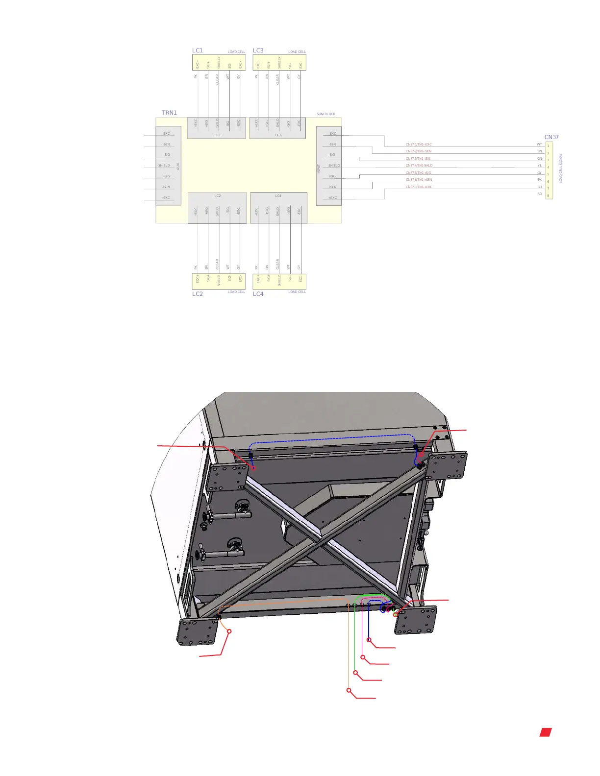
Figure 3.57. Wiring diagram showing connections from the load cell cables to the summing block.
3. Loosen all cable grips from the cables. There are 14 in total.
4. Remove the cables from the unit (Figure 3.58). Note: Attach a cable router to the end
of each of the cables before removing to allow you to easily replace the new cables.
Rear left load cell cable
Rear left load cell cable
Front left load cell cable
Front left load cell cable
Front right load cell cable
Front right load cell cable
Rear right load cell cable
Rear right load cell cable
Figure 3.58. Removing the load cell cables from the DynaDrive unit.
Thermo Scientific 36DynaDrive S.U.B. Service Guide





 To Next Page