Table 22. Removal steps of base cover and PC Card/ExpressCard (or ExpressCard/Smart
Card) bezel assembly (continued)
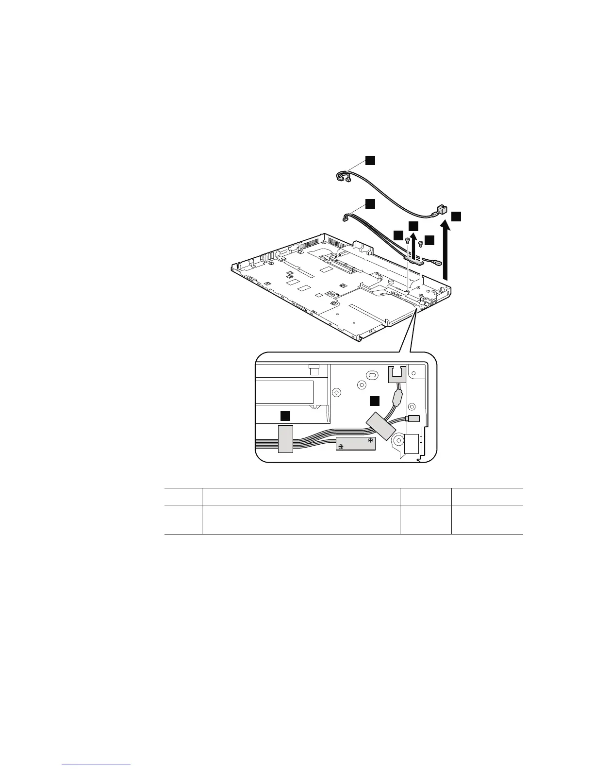
Remove the RJ11 cable a and the optical drive switch cable b as in this
figure.
In step 2, strip the securing taps off.
3
3
4
5
2
2
a
b
Step Screw (quantity) Color Torque
3 M2 × 3 mm, flat-head, nylon-coated (2) Silver 0.167 Nm(1.7
kgfcm)
116 ThinkPad R500 Hardware Maintenance Manual