Appendix A
50 HA0278T Rev H Dec 2016
A.1.2 Digital/User Inputs
The digital inputs used in the controller are of the standard CMOS logic gate type with
TTL compatible input levels and a built-in pull-up resistor (10 kOhm to +5V). They can
be connected directly to mecha nical switches, open-collector type outputs or most
type of logic outputs.
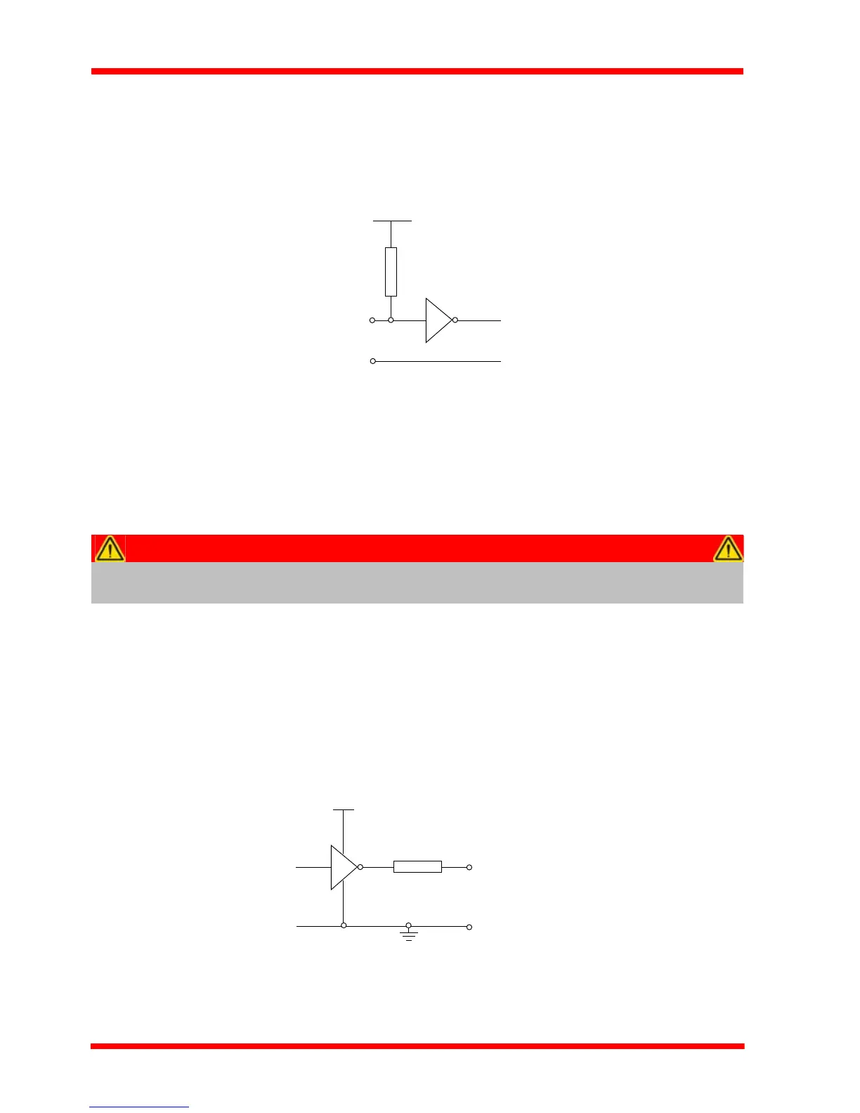
Fig. A.4 Digital Input Schematic (protection circuitry not shown)
When connected to a switch, the inputs will read as logic LOW if the switch is open
circuit and HIGH if the switch is closed. When connected to a logic output, or any other
voltage source, the input is guaranteed to read LOW if the voltage is above 2.4V and
HIGH when the output is below 0.8 V. Please see the LLGetStatusBits method in the
APTServer helpfile for details on how to control these logic IO.
A.1.3 Trigger Output
The trigger output is different from the rest of the digital outputs in that it is a 5V CMOS
logic gate with a series 1 kOhm resistor for protection. It behaves as + 5V voltage
source with 1 kOhm in series when the outputs is a logic HIGH, and 1 kOhm to ground
when it is a logic LOW. The 1 kOhm resistor limits the current to 5 mA maximum for
any load as long as the o utput is not conn ected to voltages outside the 0 V to +5 V
range.
Fig. A.5 Trigger Output Schematic
Caution
The voltage applied to the digital inputs must be within the range
0 V to 5.5 V DC, or damage to the inputs may occur.