51
Two-, and Three-Channel Stepper Motor Controller
As this output is actively driven, it can be connected, for example, to an oscilloscope
without a need for an external pull-up resistor. It can also be used to d rive most
optocouplers.
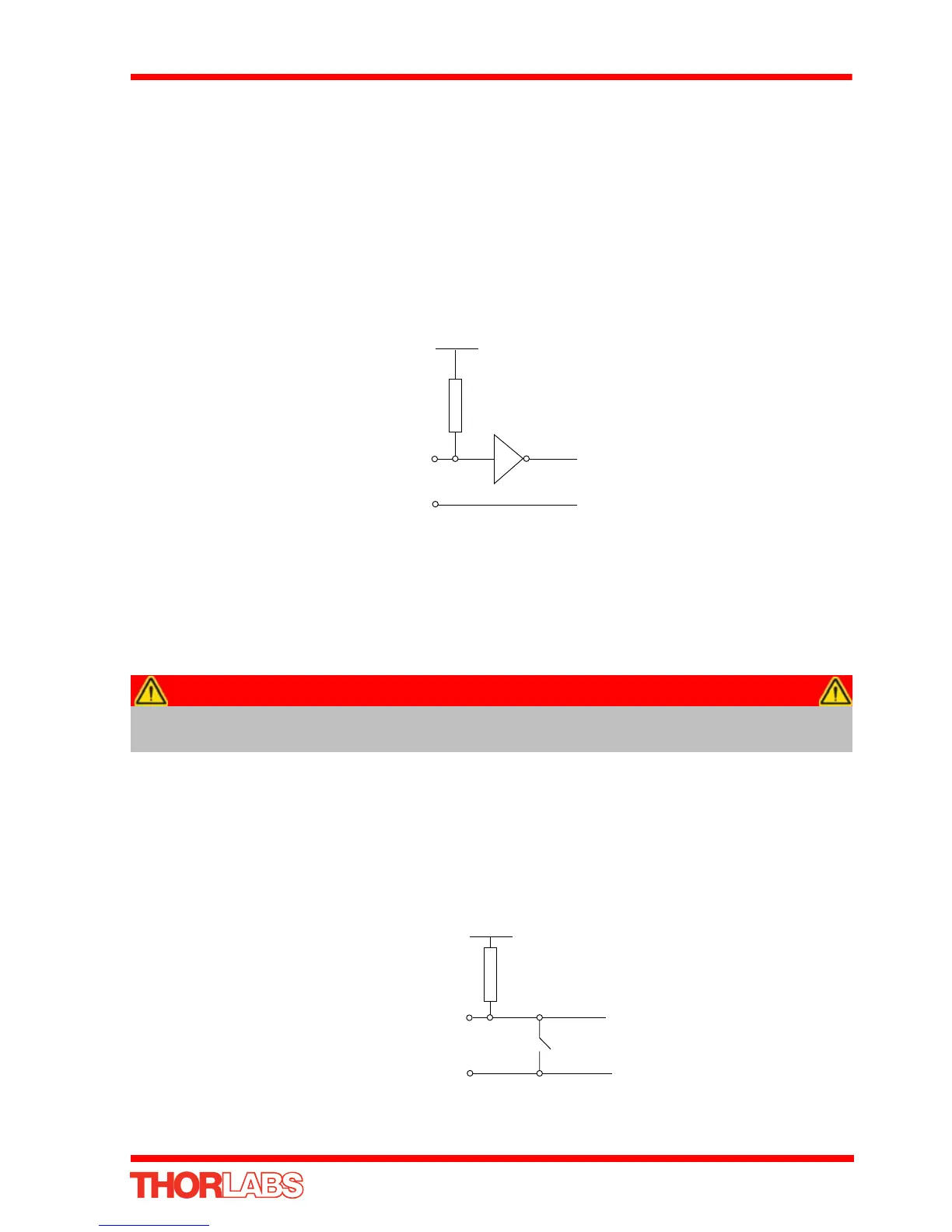
A.1.4 Trigger Input
The Trigger inputs are ekectrically identical to the digital inputs (i.e. a standard CMOS
logic gate type with TTL compatible input levels and a built-in pull-up resistor,
10 kOhm to + 5V). They can be connected directly to mechanical switches, open-
collector type outputs or most type of logic outputs.
Fig. A.6 Trigger Input Schematic (protection circuitry not shown)
When connected to a switch, the inputs will read as logic LOW if the switch is open
circuit and HIGH if the switch is closed. When connected to a logic output, or any other
voltage source, the input is guaranteed to read LOW if the voltage is above 2.4V and
HIGH when the output is below 0.8 V.
A.1.5 Jog Inputs
The jog inputs used in the controller are of the standard CMOS logic gate type with
TTL compatible input levels and a built-in pull-up resistor (10 kOhm to +5V). They can
be connected directly to mech anical switches, open-collector type outputs or most
type of logic outputs.
Fig. A.7 Jog Input Schematic (protection circuitry not shown)
Caution
The voltage applied to the trigger inputs must be within the range
0 V to 5.5 V DC, or damage to the outputs may occur.
10K
User 0V (Pin 9)
5V
Jog IN (Pin 2)
 Loading...


