53
Two-, and Three-Channel Stepper Motor Controller
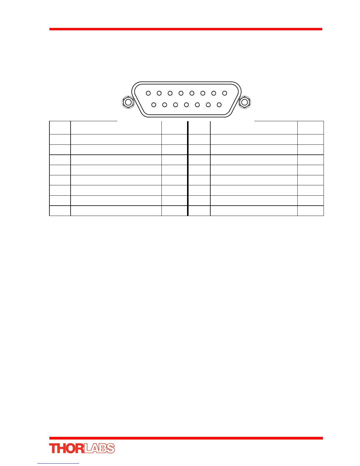
A.3 Rear Panel MOTOR DRIVE Connectors
The ‘MOTOR DRIVE ’ is a 15-Pin D-Type, Female connector that provides connection
to the motors. The pin functions are detailed in Fig. A.9. In each case the signal must
be referenced to the indicated return pin in order to be true.
Fig. A.9 DRIVE CHANNEL Connector Pin Identification
A.4 Rear Panel INTERCONNECT Connector
A.4.1 Pin Identification
The INTERCONNECT terminal is a male, 9 pin D-Type. It is intended for future use
with RS232 communications but is not implemented at present. Serial
communications must be achieved via a virtual Comms port - see Appendix B
Pin Description Return Pin Description Return
1 Encoder A +ve 9 CW Limit Stwitch
2 Encoder A -ve 10 CCW Limit Switch
3 Encoder B +ve 11 0V User
4 Encoder B -ve – 12 For Future Use
5 5V User – 13 For Future Use
6 For Future Use – 14 Motor Phase B +
7 Motor Phase B - – 15 Motor Phase A +
8 Motor Phase A - –