© 2013 Thorlabs GmbH
5 Specifications
477
5.4.5 Flange Back Distance
Calculating the flange back distance
Maximum immersion depth for lenses
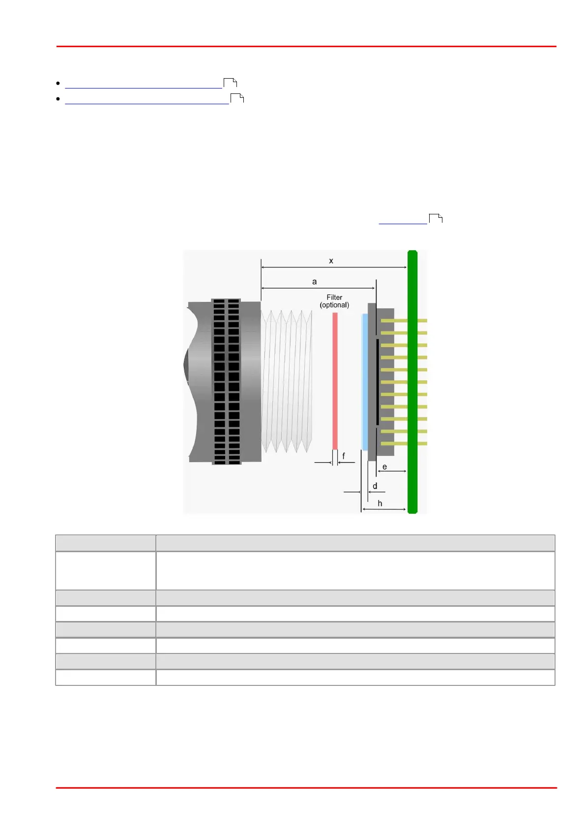
5.4.5.1 Calculating the Flange Back Distance
To correctly determine the flange back distance of a DCx camera, you need to consider the distance between the
lens flange and the active area of the sensor and, additionally, the type and thickness of any materials inserted into
the optical path.
The "distance in air" between the threaded flange and the active area is 17.526 mm with C-mount lenses and
12.526 mm with CS-mount lenses.
This "mechanical distance" can change due to the material-specific refractive index of the inserted materials. The
glass cover of the sensor and all filters inserted into the optical path (see Filter types table) must be taken into
account in the calculation.
Calculating the flange back distance (schematic illustration)
Distance from threaded flange to active sensor area (flange back distance)
17.526 mm
*1
for C-mount
12.526 mm
*1
for CS-mount
Distance from threaded flange to PCB
Distance from active sensor area to PCB
Thickness of the glass cover of the sensor
Filter thickness (optional)
Maximum sensor height above the PCB
*
1
This distance describes the equivalent in air (see introduction above)
477
478
480