© 2015 Thorlabs
2 Getting Started
9
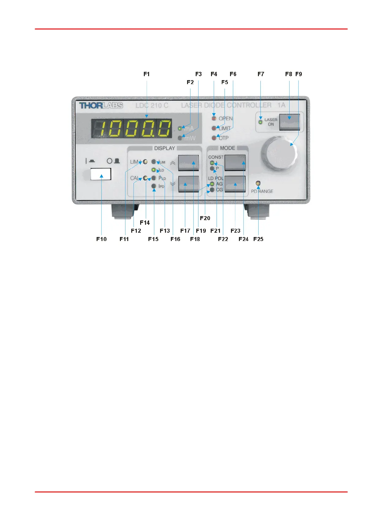
2.3 Operating elements
Front Panel
F1 - 5-digit LED display
F2 LED "mA" Current display in mA
F3 LED "mW" Power display in mW
F4 LED "OPEN" No laser diode connected, or Interlock open
F5 LED "LIMIT" Adjusted current limit reached
F6 LED "OTP" Overtemperature protection is active
F7 LED "LASER ON" Laser current is switched on
F8 Key "LASER ON" On / Off switch for the laser current
F9 - Knob for adjusting the current or power set value
F10 - Line switch (ON / OFF)
F11 LIM I Potentiometer for setting the current limit
F12 CAL Potentiometer for calibrating the power display
F13 LED "ILD" Display shows the laser current
F14 LED "PLD" Display shows the optical power
F15 LED "IPD" Display shows the photodiode current
F16 LED "ILIM" Display shows the current limit
F17 Key “DOWN” Select the parameter to be displayed
F18 Key “UP” Select the parameter to be displayed
F19 LED "AG" Selected laser polarity: anode grounded
F20 LED "CG" Selected laser polarity: cathode grounded
F21 LED "P" Constant power mode
F22 LED "I" Constant current mode
F23 Key "LD POL" Select laser polarity: anode grounded or cathode grounded
F24 Key "CONST" Select constant current mode or constant power mode
F25 PD RANGE Potentiometer for setting the photodiode current range

 Loading...


