© 2015 Thorlabs
3 Operating Instruction
13
Attention
A wrong polarity of the battery may destroy the photodiode due to a forward current flowing
through it!
3.1.3 Interlock
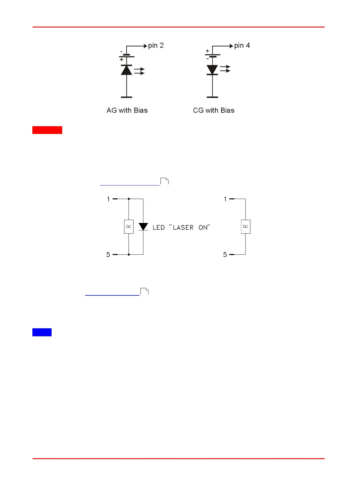
Pin 1 and pin 5 of the "LD OUT" jack (R6) are the interface of the interlock circuit.
The interlock output represents a current source, while the voltage across the external circuit,
connected to pin 1 and 5, is being observed. As soon as this voltage rises above a certain
threshold (~2.5V), the external circuit is considered as "open", the laser current output is
disabled and the LED "OPEN" (F4) lights up .
Pin 1 and pin 5 must be connected externally by a short cut wire, by a circuit (total resistance
<430 W) or by a LED (anode to pin 1, cathode to pin 5, connect in parallel resistor R=1 kW). A
connected LED lights up when the laser current is switched on (LASER ON).
Note
Do not use blue LED due to their high forward voltage
Thorlabs Laser Diode Mounts use the interlock current for indication "LD ON". When using a
Thorlabs TCLDM9 or LM14S2 laser diode mount, interlock functionality can be easily used for
emergency switch-off of the laser by connecting an opening contact to the jack located on the
laser mount. For details, please refer to the appropriate laser diode mount manual.
11
9

 Loading...


