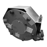
Installation and Operational Instructions
for ROBA-stop
®
-silenzio
®
Type 896.213.30
Sizes 500 – 1800
Chr. Mayr GmbH + Co. KG Tel.: +49 8341 804-0 E079 10 228 000 471
Eichenstraße 1 Fax: +49 8341 804-421 Page 12 of 17
D-87665 Mauerstetten www.mayr.com
Germany E-Mail: info@mayr.com 21/06/2012 TK/HW/GF/SU
Installation Conditions
The eccentricity of the shaft end in relation to the mounting
pitch circle must not exceed 0,2 mm.
The position tolerance of the threaded holes for the
hexagon head screws (7) must not exceed 0,2 mm.
The axial run out deviation of the screw-on surface to the
shaft must not exceed the permitted axial run out tolerance
of 0,063 mm according to DIN 42955 R.
The reference diameter is the pitch circle diameter for
securement of the brakes.
Larger deviations can lead to a drop in torque, to
continuous slipping on the rotor and to overheating.
For Size 500:
The tolerances of the hub (1) and the shaft must be
selected so that no widening of the hub (1) toothing can
occur, as widening of the toothing leads to the rotors (4 and
4.1) jamming on the hub (1) and therefore to brake
malfunctions
(recommended hub - shaft tolerance H7/k6).
The max. permitted joining temperature of 200 °C must not
be exceeded.
For Sizes 800 - 1800:
The toothed motor shaft must be designed to push fit acc.
drawing, with a toothing acc. DIN 5480.
The rotors (4 and 4.1) and brake surfaces must be oil and
grease-free.
A suitable counter friction surface (steel or cast iron) must
be used. Sharp-edged interruptions on the friction surfaces
must be avoided.
Recommended surface quality in the area of the friction
surface Ra = 1,6 µm.
In particular customer-side mounting surfaces made of
grey cast iron are to be rubbed down additionally with
fine sandpaper (grain 200 – 400), or ideally with a
sander.
The toothings of the motor shaft or the hub (1) and the
rotors (4 and 4.1) must not be oiled or greased.
Please abstain from using cleaning agents containing
solvents, as they could affect the friction material.
During longer downtimes, we recommend the use of
suitable corrosion protection measures for the mounting
surface (e.g. zinc-phosphate coating) until initial operation.
Here, the influence of the corrosion protection measure on
the braking behaviour must be checked.
Installation
1. For Size 500:
Mount the hub (1) onto the shaft with the inserted key, bring
it into the correct position (the length of the key should lie
over the entire hub) and secure it axially, e.g. using a
locking ring.
For Sizes 800 - 1800:
Push the hub (1) with the recess first up to contact onto the
shaft shoulder of the toothed shaft and secure it axially, e.g.
using a locking ring.
2. For Sizes 500 and 800:
Push rotor 1 (4) by hand onto the hub (1) (the rotor collar
should be facing away from the machine wall).
Check that the toothing moves easily.
For Sizes 1300 and 1800:
Push rotor 1 (4) by hand onto the hub (1) (the rotor collar
should be facing in the direction of the machine wall).
Check that the toothing moves easily.
3. Turn the thrust springs (13) anti-clockwise into the stepped
bores of the intermediate disk (6) (for number of pieces, see
Parts List).
4. Push the brake body with the intermediate disk (12) and
rotor 2 (4.1) across the hub (1). Join the toothing carefully
and check that it moves easily. Do not damage the toothing.
5. Insert the hexagon head screws (7) including the washers
(8) into the brake body and tighten them all around evenly
using a torque wrench and a tightening torque (acc.
Technical Data).
6. Check the air gaps acc. Technical Data
The nominal air gap "a" on a de-energised brake and the
individual air gaps "b" on a released brake must be given.
7. Produce the electrical connection.