Installation and Operational Instructions
for ROBA-stop
®
-silenzio
®
Type 896.213.30
Sizes 500 – 1800
Chr. Mayr GmbH + Co. KG Tel.: +49 8341 804-0 E079 10 228 000 471
Eichenstraße 1 Fax: +49 8341 804-421 Page 11 of 17
D-87665 Mauerstetten www.mayr.com
Germany E-Mail: info@mayr.com 21/06/2012 TK/HW/GF/SU
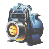
Application
ROBA-stop
®
-silenzio
®
for use as a holding brake with
occasional EMERGENCY STOP braking actions
Horizontal brake axis.
The max. permitted speed and friction work values, see
Technical Data, must be observed.
Design
The ROBA-stop
®
-silenzio
®
is a spring applied,
electromagnetically releasing safety brake.
It is designed for installation into gear elevator machines for use
as a holding brake with occasional EMERGENCY STOP braking
actions.
On dimensioning, the braking torque, the speed as well as the
permitted friction work in case of EMERGENCY STOP need to
be taken into consideration for safe holding of the load torque
and safe compliance with the required braking distance.
Furthermore, the ROBA-stop
®
-silenzio
®
can be used as a brake
assembly having an effect on the drive sheave shaft, as part of
the protective assembly against excessive upward-moving cage
speeds (EN 81-1 Section 9.10.2).
Please observe the appendix (application range, conditions,
guidelines) in the EC Type Examination Certificate (EC directive
95/16/EC).
Moreover, the brake fulfils all criteria as a brake element having
an effect on the drive sheave shaft, as part of the protective
assembly against inadvertent movement of the elevator cage
(EN 81-1 Section 9.11.3).
Here, please observe the notes in the appendix (application,
area, conditions, guidelines) of the Type Examination Certificate
(inspection specification EN 81-1:1998+A3:2009(D))
In order to guarantee the maximum braking distance (EN 81-1
Section 9.11.5) while both brakes take effect, an inspection of
the protective equipment including all controls and brake times
(detector / controls / brake) is necessary. The respective
standards, regulations and directives must be observed.
Function
ROBA-stop
®
-silenzio
®
brakes are spring applied,
electromagnetic safety brakes.
Spring applied function (brake):
In de-energised condition, thrust springs (10/11) press against
the armature disk (3). The rotor 2 (4.1) is held between the
armature disk (3) and the intermediate disk (12), the rotor 1 (4)
between the intermediate disk (12) and the machine wall via
frictional locking. The braking torque is introduced into the shaft
via the rotor toothing (4 and 4.1) and the hub (1).
Electromagnetic function (release):
Due to the magnetic force of the coil in the coil carrier (2), the
armature disk (3) is attracted against the spring force to the coil
carrier (2) and the intermediate disk (12) is pressed against the
collar of the distance bolts (9) via the thrust springs (13).
The brake is released and the brake rotors (4 and 4.1) with the
hub (1) can rotate freely.
Safety brake function:
The ROBA-stop
®
-silenzio
®
brakes reliably and safely in the event
of a power switch-off, a power failure or an EMERGENCY
STOP.
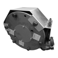
State of Delivery
The brakes are pre-assembled.
The release monitoring devices (6) are mounted and set
manufacturer-side.
Included loose in delivery are:
- Hub (1)
- Rotor (4)
- Cap screws (5.1)
- Washers (5.2)
- Hexagon head screws (7)
- Washers (8)
- Thrust springs (13)
- Cover plate (14)
- Cap screws (15)
Please check the state of delivery immediately according to the
Parts List.
mayr
®
will take no responsibility for belated complaints.
Please report transport damage immediately to the deliverer.
Please report incomplete delivery and obvious defects to the
manufacturer.
The screws (16) marked red must be removed
before initial operation of the brake.
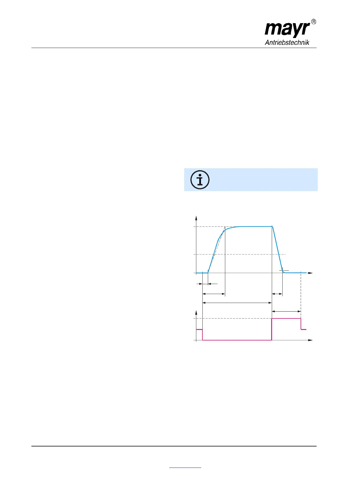
Torque-Time Diagram
Key
M
Br
= Braking torque
M
L
= Load torque
t
1
= Connection time
t
11
= Response delay on connection
(≙t
0
acc. ESV 762/1)
t
2
= Separation time
t
4
= Slipping time + t
11
t
über
= Overexcitation time
U
nenn
= Coil nominal voltage
U
halte
= Holding voltage
U
über
= Overexcitation voltage
U
halte
U
über
M
Br
0,1 x M
Br
M
L
t
11
t
1
t
2
t
4
t
über
U
M
t
t