Installation and Operational Instructions
for ROBA-stop
®
-silenzio
®
Type 896.213.30
Sizes 500 – 1800
Chr. Mayr GmbH + Co. KG Tel.: +49 8341 804-0 E079 10 228 000 471
Eichenstraße 1 Fax: +49 8341 804-421 Page 15 of 17
D-87665 Mauerstetten www.mayr.com
Germany E-Mail: info@mayr.com 21/06/2012 TK/HW/GF/SU
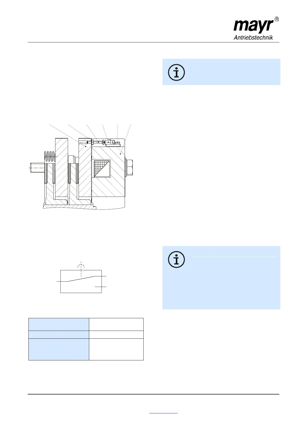
Release Monitoring (6), Fig. 13
The ROBA-stop
®
-silenzio
®
brakes are delivered with
manufacturer-side set release monitoring.
A microswitch (Item 6.1) emits a signal for every brake signal
condition change: "brake opened" or "brake closed“
On initial operation:
Connection as NO contact (black and blue strands).
The customer is responsible for a signal evaluation of both
conditions.
From the point at which the brake is energised, a time span of
three times the separation time must pass before the
microswitch signal on the release monitoring is evaluated.
Fig. 13
Function
When the magnetic coils are energised in the coil carrier (2), the
armature disk (3) is attracted to the coil carrier (2).
The microswitch (6.1) emits the signal to indicate that the brake
is released.
Wiring Diagram Microswitch (6.1):
Microswitch Specification
Characteristic values for
measurement:
Minimum switching capacity:
Recommended switching
capacity:
for maximum lifetime
and reliability
24 V, 10...50 mA
DC-12
DC-13 with free-wheeling
diode!
Usage category acc. IEC 60947-5-1:
DC-12 (resistance load), DC-13 (inductive load)
Manufacturer-side Adjustment and Functional
Inspection of the Microswitch (6.1), see Fig. 13:
The brake is mounted, secured with a
tightening torque acc. Technical Data and the
coil is de-energised.
1. Turn the hexagon head screw (6.3) in the direction of the
switch (6.1) up to the microswitch tappet.
2. Tighten the hexagon nut (6.4), so that the hexagon head
screw (6.3) is placed under pre-tension by the spring washer
(6.5).
3. Put a feeler gauge 0,20 mm (loose sensor plate) between
the switch tappet (6.1) and the hexagon head screw (6.3).
4. Connect the inspection or measurement device (diode
inspection) to the NO contact black/blue.
5. Turn the hexagon head screw (6.3) in the direction of the
switch (6.1) up to the signal "ON", turn it back to the signal
"OFF" and counter the hexagon head screw (6.3) with the
hexagon nut (6.4).
6. Energise brake Signal "ON",
De-energise brake Signal "OFF",
Re-adjust if necessary and repeat the inspection
(align 3 to 5 times).
7. Inspect using feeler gauge 0,25 mm
a) Energise the brake Signal "ON",
b) De-energise the brake Signal "ON"
8. Inspect using feeler gauge 0,20 mm
a) Energise the brake Signal "ON",
b) De-energise the brake Signal "OFF"
9. Paint Items 6.2, 6.3 and 6.4 with sealing lacquer.
Customer-side Inspection after Mounting
The customer-side contact is an NO contact.
Please inspect the release monitoring units:
Brake de-energised Signal "OFF",
Brake energised Signal "ON"
Microswitches cannot be guaranteed fail-safe.
Therefore, please ensure appropriate access
for replacement or adjustment.
The switching contacts are designed so that
they can be used for both small switching
capacities and medium ones. However, after
switching a medium switching capacity, small
switching capacities are no longer reliably
possible.
In order to switch inductive, capacitative and
non-linear loads, please use the appropriate
protective circuit to protect against electric arcs
and unpermitted loads!
1
4
2
NC Contact
grey onnection
Connection when
brake closed
c
NO Contact
blue connection
Connection when
brake released
COM Contact
lack cb onnection