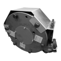
Installation and Operational Instructions
for ROBA-stop
®
-silenzio
®
Type 896.213.30
Sizes 500 – 1800
Chr. Mayr GmbH + Co. KG Tel.: +49 8341 804-0 E079 10 228 000 471
Eichenstraße 1 Fax: +49 8341 804-421 Page 16 of 17
D-87665 Mauerstetten www.mayr.com
Germany E-Mail: info@mayr.com 21/06/2012 TK/HW/GF/SU
Braking Torque
The (nominal) braking torque is the torque effective in the shaft
train on slipping brakes, with a sliding speed of 1 m/s referring to
the medium friction radius.
The brake is loaded statically when used as a service brake and
loaded dynamically in EMERGENCY STOP operation (part of
the brake equipment against overspeed or inadvertent
movement of the elevator cage). Respectively, there are different
speed values for the friction material, which in practice also
leads to different friction values and therefore braking torques.
The braking torque is dependent on the respective run-in
condition of the friction surfaces.
We recommend allowing the friction surfaces to run in when
installed and under permitted loads.
Friction materials develop their optimum effect only under speed
at the appropriate contact pressure, as continuous regeneration
of the friction surface then takes place (torque consistency).
Furthermore, friction materials (synthetic resin bonded rubber
mixtures) are subject to aging, which is also influenced, among
other things, by higher temperatures and other ambient
influences. We recommend regular inspection of the braking
torque (1 x per year) including the respective dynamic braking
actions.
Noise Damping
The noise damping used here was set and
adjusted manufacturer-side. However, this
component is subject to aging dependent on
the application or operational conditions (torque
adjustment, switching frequency, ambient
conditions, system vibrations etc.)
Replacing the damping element is only
permitted at the mayr
®
site of manufacture.
Brake Inspection (before brake initial operation)
Air Gap Inspection (Figs. 2, 4, 6, 8 and 9):
Air gap "a" (brake de-energised) acc. Technical Data:
Nominal air gap -0,1 mm / +0,15 mm.
Min. individual air gaps "b" (brake energised) acc.
Technical Data.
Braking Torque Inspection:
Please compare the requested braking torque with the
torque stated on the Type tag (18).
Release Function Inspection
By energising the brake via battery operation, to guarantee
emergency escape for passengers during a power failure or
manually using the emergency hand release (dependent on
Type).
Switching function inspection (NO contact)
Energised brake Signal "OFF"
De-energised brake Signal "ON"
Maintenance
ROBA-stop
®
-silenzio
®
brakes are mainly maintenance-free.
The friction linings are robust and wear-resistant. This ensures a
particularly long service lifetime. However, the friction linings are
subject to operational wear on frequent EMERGENCY STOP
braking actions. Normally, such occurrences are recorded and
saved by the elevator control, or they require the intervention of
qualified personnel. When carrying out this maintenance work
(especially when taking DIN EN 13015 Appendix A into account),
the causes of the malfunction must be determined, assessed
and removed by specialist personnel. Causal events such as the
air gap can be checked and respective measures can be taken.
The following checks must be carried out following the regular
inspection intervals:
Braking torque or retardation inspection.
Inspection of air gap in braked condition.
Inspection of toothing backlash from the motor shaft or the
hub (1) to the rotor (4/4.1).
Max. permitted toothing backlash 0,3°.
In order to inspect the wear condition of the
rotors (4 and 4.1), please measure the air gap
"a", see Figs. 2, 4, 6, 8.
If the brake maximum air gap (acc. Technical
Data) has been reached, meaning that the
friction linings are worn down, the braking
torque is lost and the rotors (4 and 4.1) must be
replaced.
Brake de-installation is carried out by following
the instructions in the section Installation (page
10) backwards.
Before Replacing the Rotors
Clean the brake and remove abraded particles using
compressed air.
Do not inhale brake dust (wear a dust mask).
Measure the rotor thickness "new condition" (nominal size
dimension acc. Technical Data).
Replacing the Rotors (4 and 4.1)
Rotor (4 and 4.1) replacement is carried out by following the
Brake Installation instructions backwards.
The drive brake must be load-free on hoist
drives. Otherwise there is a danger of load
crashes!