2-5
Chapter 2
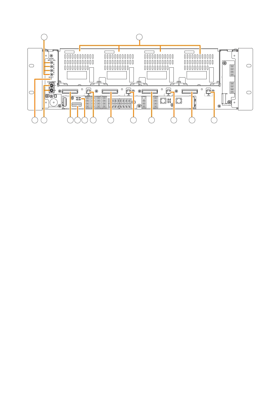
NOMENCLATURE AND FUNCTIONS
24. Audio input volume controls
Adjust the input volume of each input channel.
Rotating the control fully counterclockwise mutes
the input sound source connected to that channel.
25. Module slots
Accommodate the VX-015DA, VX-030DA, or VX-
050DA, Digital Power Amplier Module. Up to 4
modules can be installed to the VX-3004F, up to 3
to the VX-3008F, and up to 2 to the VX-3016F.
26. Reset key
Pressing this key reactivates the VX-3000F.
27. ID switch
Sets the VX-3000F's ID number (device number).
28. DA control link connector
Connect this connector to the DA control link
connectoroftheinstalleddigitalpoweramplier
module.
29 . DIP switch
[VX-3004F]
•Switches1–6
These switches are not used.
•Switch7
Used when conrming the rmware version.
(See p. 4-2.)
•Switch8
Used to set the IP address. (See p. 3-8.)
[VX-3008F]
•Switches1–3
Used to allocate speaker lines. (See p. 3-5.)
•Switches4–6
These switches are not used.
•Switch7
Used when conrming the rmware version.
(See p. 4-2.)
•Switch8
Used to set the IP address. (See p. 3-8.)
[VX-3016F]
•Switch1
Used to place the unit in 2 channel mode
operation. (See p. 3-5.)
•Switches2–6
These switches are not used.
•Switch7
Used when conrming the rmware version.
(See p. 4-2.)
•Switch8
Used to set the IP address. (See p. 3-8.)
Note
By default, switches 1 – 7 are set to OFF, and
switch 8 to ON.
30. Impedance initialize key
Press this key to acquire the initial value of the
speaker line impedance as failure detection is
executed on the basis of the impedance change.
31. DA output link connector
Connect this connector to the DA output link
connectoroftheinstalleddigitalpoweramplier
module.
24 25
26 27 28 28 28 2829 30 31 313131
[Front panel detached]