3-7
Chapter 3
INSTALLATION AND SETTING PROCEDURES (HARDWARE)
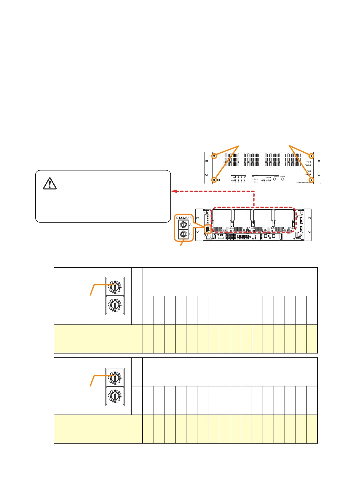
Step 1. Detach the front panel.
Remove4xingscrewsforfrontpanelanddetach
the front panel.
Notes
• When setting theID number formultiple VX-3000F units, assign different numbers toeach unit. The ID
number that can be used must not exceed the actual number of VX-3000F units set using the VX-3000
Setting Software.
• IfanIDnumberisduplicated,thentheVX-3000FunitsassignedthatnumbercannotbecontrolledbytheVX-
3000F system.
• TheVX-3000FsettoID"0"playsaroleofaleaderinthewholesystem,displayingthe"GENERALFAULT"
indication and outputting its signal when malfunction occurs within the system.
• InasingleVX-3000Fconguration,settheIDnumberto"0."
[ID number setting]
Note: The ID number is set to No. 0 by default.
ID switch
A 0
B 0 1 2 3 4 5 6 7 8 9 A B C D E F
ID number 0 1 2 3 4 5 6 7 8 9 10 11 12 13 14 15
Arrowhead
ID NUMBER
A
B
ID switch
A 1
B 0 1 2 3 4 5 6 7 8 9 A B C D E F
ID number 16 17 18 19 20 21 22 23 24 25 26 27 28 29 30 31
Arrowhead
ID NUMBER
A
B
VX-3000F front
Fixing screws for front panel
1
2
ID Switch
VX-3000F front
(Front panel detached)
There is a high voltage section inside the power
amplifier's filter. Never insert your finger or
metallic objects inside the unit.
Step 3. Replace the front panel.
Secureitusing4xingscrewsforfrontpanel.
2.3. The ID Number Setting
Step 2. Set the ID switches.