3-58
Chapter 3
INSTALLATION AND SETTING PROCEDURES (HARDWARE)
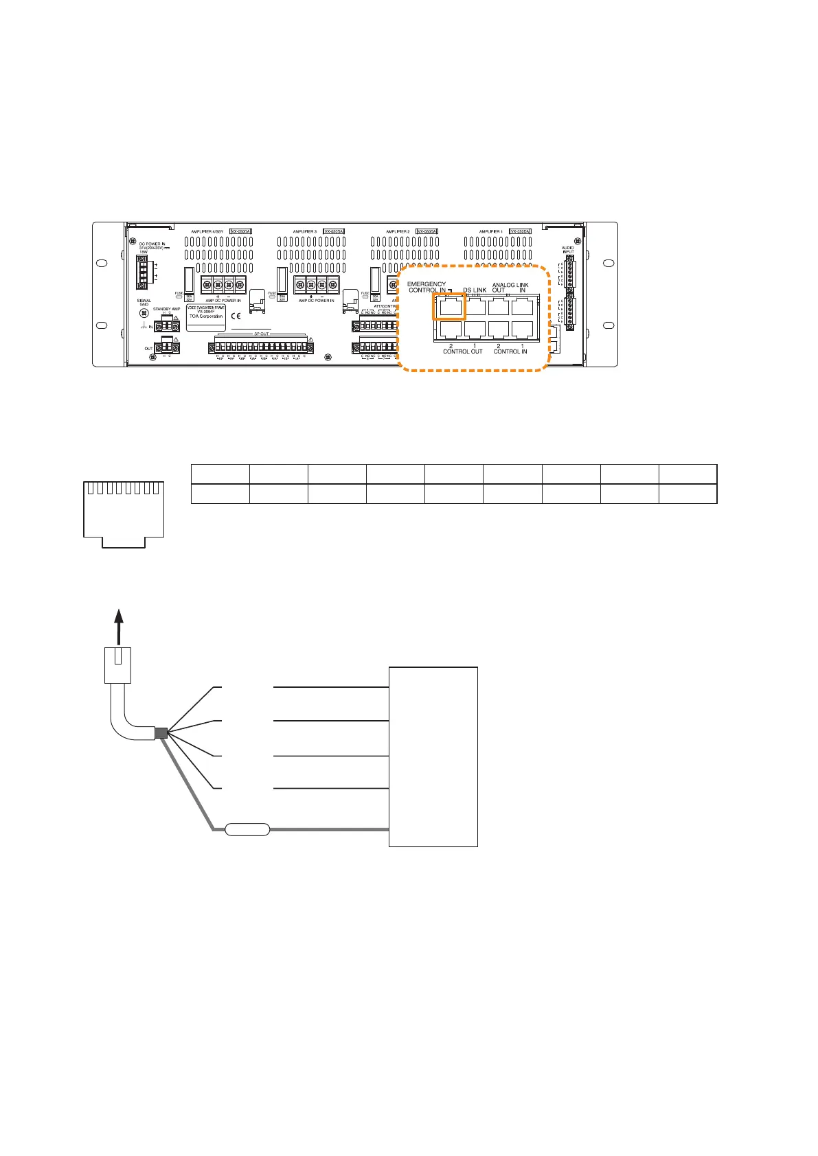
4.6. Emergency Control Input Terminal Connections
The Emergency control input terminals are voltage inputs. Cable disconnection and short-circuit can be
detected using these input terminals.
Use the VX-3000 Setting Software to set the applications and signal input type. (See the separate Setting
Software Instructions, "SURVEILLANCE SETTINGS," "Failure Pattern Settings," "Control Inputs Event
Settings.")
The RJ45's pin arrangement and pin functions are shown below.
[EMERGENCY CONTROL IN]
Connection example
Pin1 Pin2 Pin3 Pin4 Pin5 Pin6 Pin7 Pin8 Shield
FDS_A+ FDS_A–
NC
FDS_B+ FDS_B–
NC NC NC Com
VX-3000F
87654321
RJ45 connector
pin No.
To VX-3000F
FDS_A+
FDS_A–
Shield
(Com)
FDS_B–
FDS_B+
FDS
DC 24 V (–)
DC 24 V (+)
DC 24 V (–)
DC 24 V (+)