3-19
Chapter 3
INSTALLATION AND SETTING PROCEDURES (HARDWARE)
8
7
6
5
4
3
2
1
TERMINATION
CPU OFF
LEVEL METER
COMMUNICATION
UNIT ID
OnOff
DIP SWITCH
RM-200SF rear
Inch screw (combination drive) No.6-32 x 1/4 (1)
Tooth lock washer (1)
Tapping screw
(Phillips) 3 x 8 (4)
3.7. Compressor Function Setting
This change should only be performed by a qualified professional
electrician. If users open the unit case or modify the unit, this may
cause fire or electric shock.
WARNING
The compressor function enables even large signals to be broadcast without distortion. (This function is factory-
preset to ON.)
Notes
• Turnoffthepowerbeforestartingthiswork.
• Toavoiddamagefromstaticelectricity,nevertouchthepartsonthecircuitboard.
[RM-200SF]
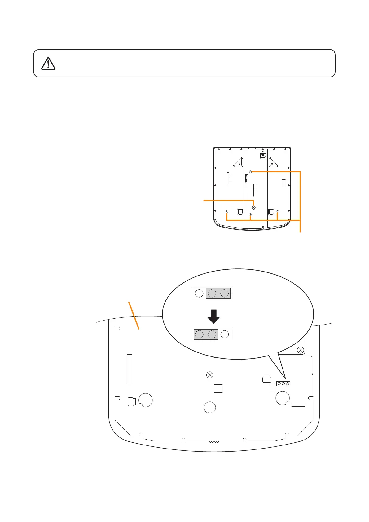
Step 1. Unscrew 5 screws in the gure at right, then
detach the RM -200SF's rear plate.
Note
Notethespecicshapesofthedifferentscrews.
Step 2. Set the jumper's position (JP301) on the circuit board attached to the front case as shown below.
Step 3. Replace the RM-200SF's rear plate.
Note:Notethespecicshapesofthedifferentscrewswhenreplacingtherearplate.(SeeStep 1.)
JP301
RM-200SF inner circuit board
JP301
When the compressor
function is used.
(Factory-preset)
When the compressor
function is not used.
JP301