3-28
Chapter 3
INSTALLATION AND SETTING PROCEDURES (HARDWARE)
3.11. RM-300X Extension with the Addition of the RM-210F
(Installed on a Flat Surface)
When adding an RM-210F Remote Microphone Extension to expand the RM-300X, use the RM-210F's
Extension cable and included Linkage Bracket to link the 2 microphones.
Up to 7 RM-210Fs can be conncted to an RM-300X.
After DIP switch setting completion, follow the procedures below.
[Mounting hardware (supplied with the RM-210F)]
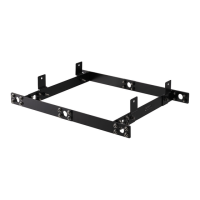
Linkage Bracket A ................................. 2
Linkage Bracket B ................................. 1
Screw ...................................................... 12
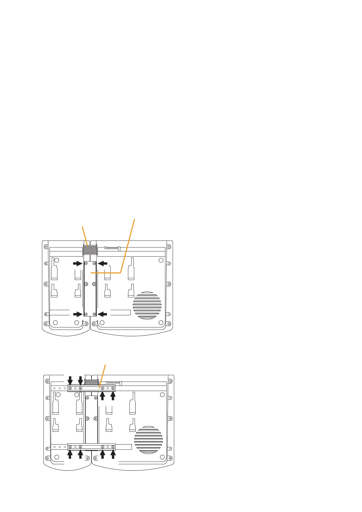
Step 1. Turn over both the RM-300X and the RM-210F, and keep them in close contact with each other.
Step 2. Connect between both units using the extension cable supplied with the RM-210F.
Step 3. Using 4 supplied screws indicated by arrows and Linkage Bracket B, link both units together.
Step 4. Using8suppliedscrewsindicatedbyarrowsand2piecesofLinkageBracketA,xbothunitssecurely.
Note: To add another RM-210F to the installed RM-210F, use the similar procedures as in this section.
Extension cable
(Supplied with RM-210F)
RM-210F
RM-300X
Linkage Bracket B
3
2
[Bottom side]
Linkage Bracket A
RM-210F RM-300X
[Bottom side]
4
Notes
• BecausetheLinkageBracketAisprovidedwith2
spare screw holes, use them to link the 2 units if the
designated screw threaded holes are damaged.
• If incorrect or loose connection is found between
both units, loosen allthe bracket xing screws to
disassemble the units and then link them again with
the screws.