2-12
Chapter 2
NOMENCLATURE AND FUNCTIONS
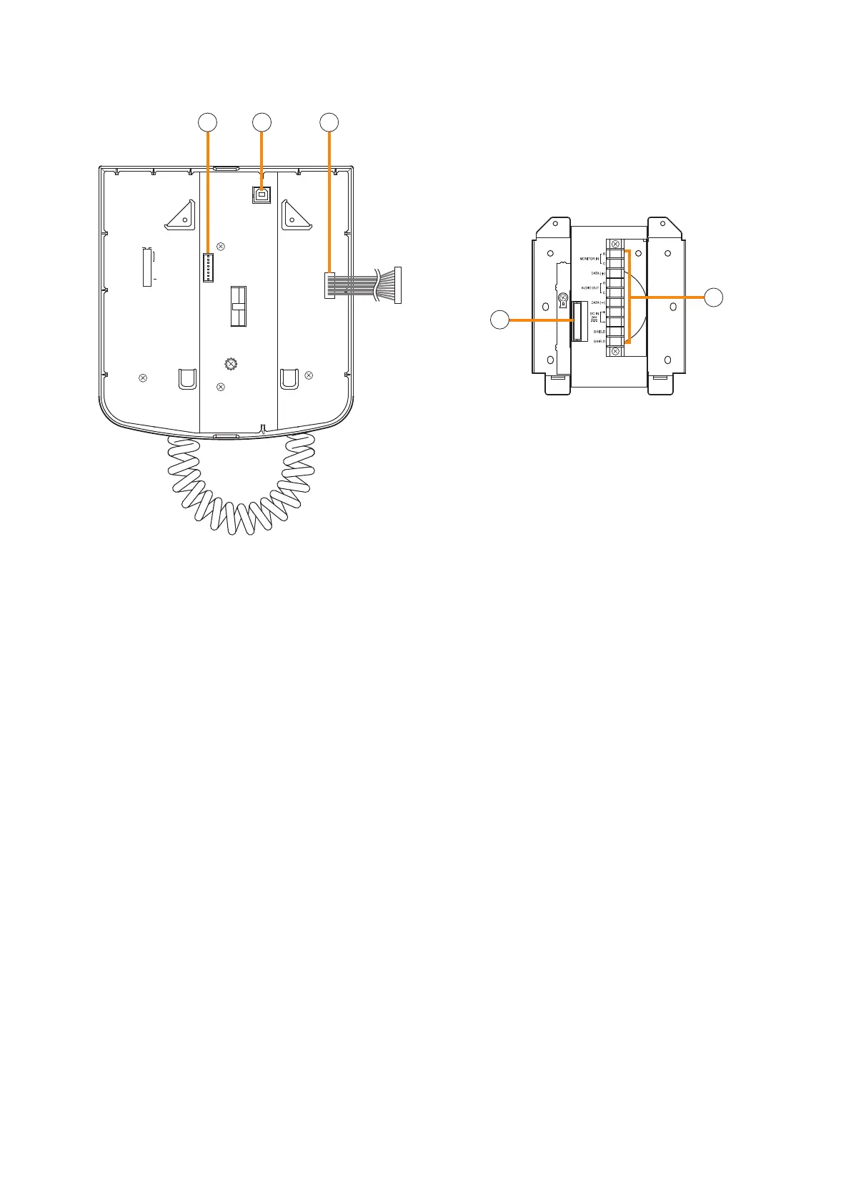
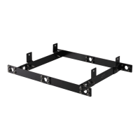
[Wall mount bracket unit (Accessory)]
23
24
[Rear]
8
7
6
5
4
3
2
1
TERMINATION
CPU OFF
LEVEL METER
COMMUNICATION
UNIT ID
OnOff
DIP SWITCH
20 21 22
20. DIP switch
Used for setting the RM-200SF unit.
•Switches1–3[UNITID]
Set the RM-200SF's device number (ID number).
(See p. 3-9.)
•Switch4[COMMUNICATION]
Sets the RM communication function. (See
p. 3-14.)
•Switch5[LEVELMETER]
Changes a broadcast status indicator (12) into
an output signal level indicator. (See p. 3 -11.)
•Switch6[CPUoff]
Sets whether the CPU off function (all-zone
emergency broadcasts) is enabled or disabled.
(See p. 3-13.)
•Switch7
Not used. Normally set to OFF .
•Switch8[TERMINATION]
Sets the termination of the RM communication
line (Control communication lines between the
VX-3000F and the RM-200SF). Normally set to
OFF.
Note
By default, switches 1 – 5 and 7 are set to OFF,
and switches 6 and 8 to ON.
21. USB te rminal
Not used.
22. Extension connector
Connect this connector to the extension connector
(23) of the Wall Mount Bracket Unit (accessory).
(See p. 3-25.)
23. Extension connector
Connect the cable extending from the RM-200SF
to this connector. (See p. 3-25.)
24. Screw terminal block
•Audiomonitorline[MONITORIN]
Connect the audio monitor input line from the
VX-3000F to the RM-200SF.
•RMcommunicationline[DATA]
Connect the control communication line between
the VX-3000F and the RM-200SF.
•Audiooutputline[AUDIOOUT]
Connect the audio signal output line from the
RM-200SF to the VX-3000F.
•DCpowerinput[DCIN24V]
Used to supply DC power from the VX-3000F to
th e RM -2 00SF.
•Shield[SHIELD]
Used for the control line through which the
VX-3000F system conrms the RM-200SF's
connection.
Be sure to connect at least one of two terminals
to the VX-3000F.