3-4
Chapter 3
INSTALLATION AND SETTING PROCEDURES (HARDWARE)
Step 1. Shut off the power.
Shut off the power when the power is supplied to
the VX-3000F unit.
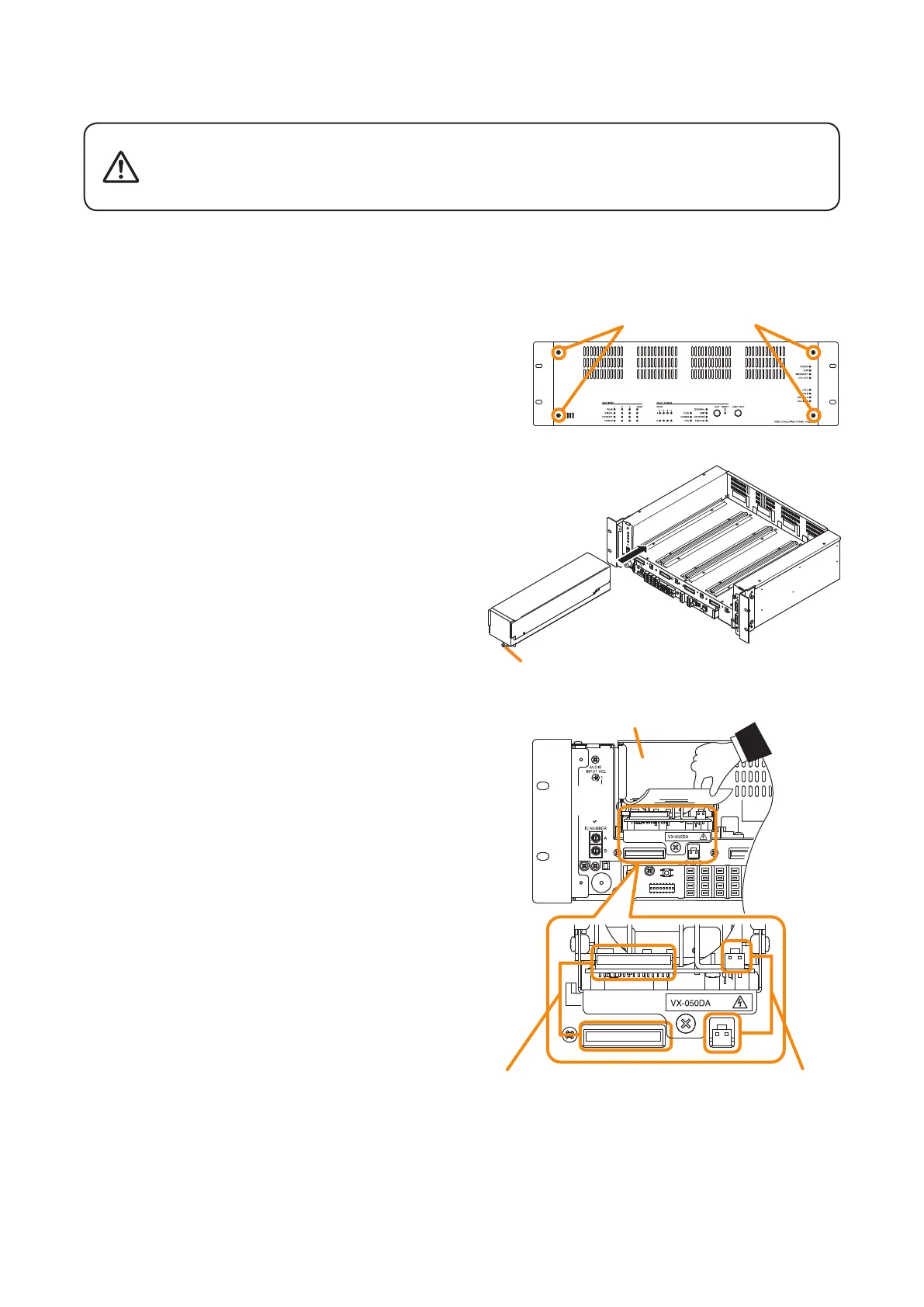
Step 2. Detach the front panel.
Remove4xingscrewsforfrontpanelanddetach
the front panel.
Step 3. Installthedigitalpowerampliermodule.
Insert the power amplier module along the
supporting runner until it will not go any further, then
secureitusingapowerampliermodulexingscrew.
Note
Usea#2bitPhilipsscrewdrivertotightenthexing
screw.
Step 4. Lift the lower portion of the lter, then connect
cables.
4-1. Connect both the power amplier module's DA
control link connector and DA output link connector
to the VX-3000F's corresponding connectors.
Usethecablessuppliedwith thepoweramplier
module.
Note
After the cable connection is complete, be sure
to push the cables against the amplier side to
prevent them from protruding so that the front panel
can be easily mounted without obstructing its work.
4-2. Replacethelter.
Step 5. When installing two or more power amplier
modules, repeat Steps 3 and 4.
Step 6. Replace the front panel.
Secureitusing4xingscrewsforfrontpanel.
VX-3000F
Fixing screws for front panel
2
3
VX-3000F
front
VX-015DA/
030DA/050DA
[Power amplifier installation procedure]
Thereisahighvoltagesectioninsidethepoweramplier'slter.Never
insertyourngerormetallicobjectsinsidetheunit.Whenattachingor
detaching the connector, never touch the internal components other
than connectors.
WARNING
4
DA control link connector DA output link connector
Filter