3-61
Chapter 3
INSTALLATION AND SETTING PROCEDURES (HARDWARE)
To other
switching hub
To other
switching hub
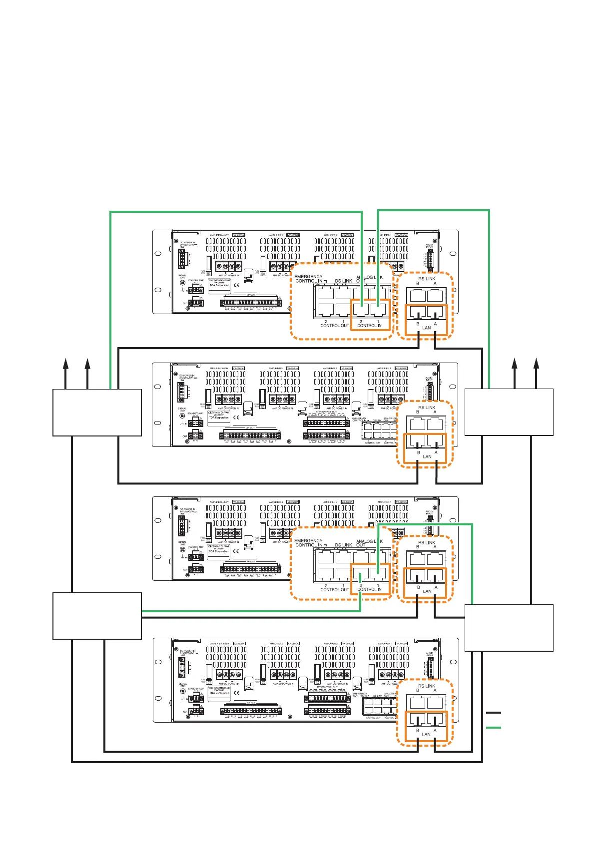
Main line
: LAN Link
: Control line
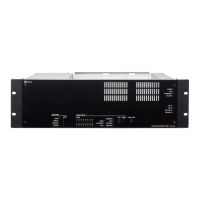
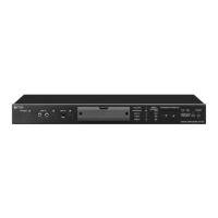
VX-3000F
VX-3000F
VX-3000F
VX-3000F
Switching hub (B-2)
Switching hub (B-1)
Switching hub (A-2)
Switching hub (A-1)
5.1.1. Redundant configuration of switching hubs
In the connection example below, the LAN Link A and B connectors of each unit are individually connected
to different switching hubs. By using switching hubs with failure status output function, if any one of switching
hubs fails or the main line breaks, such a failure can be detected.
Notes
• Upto7-levelcascadeisallowedforswitchinghubconnections.
• Afterconnectioncompletion,reactivatetheVX-3000FbypressingtheResetkeyonitsfrontpanel.
• Performspanningtreesettingwithinswitchinghubs.Forthesetting,contactyournetworkadministrator.
• The "External failure input" function needs be assigned to the unit's control input terminal to which the
switching hub's failure status output is connected. (For details, see the separate Setting Software Instructions,
"EVENT SETTINGS.")
Note: Contact your TOA dealer for more information on switching hubs.
 Loading...